This thread has been locked.

If you have a related question, please click the "Ask a related question" button in the top right corner. The newly created question will be automatically linked to this question.

THS4531 Instability

Other Parts Discussed in Thread: THS4531

Hello,

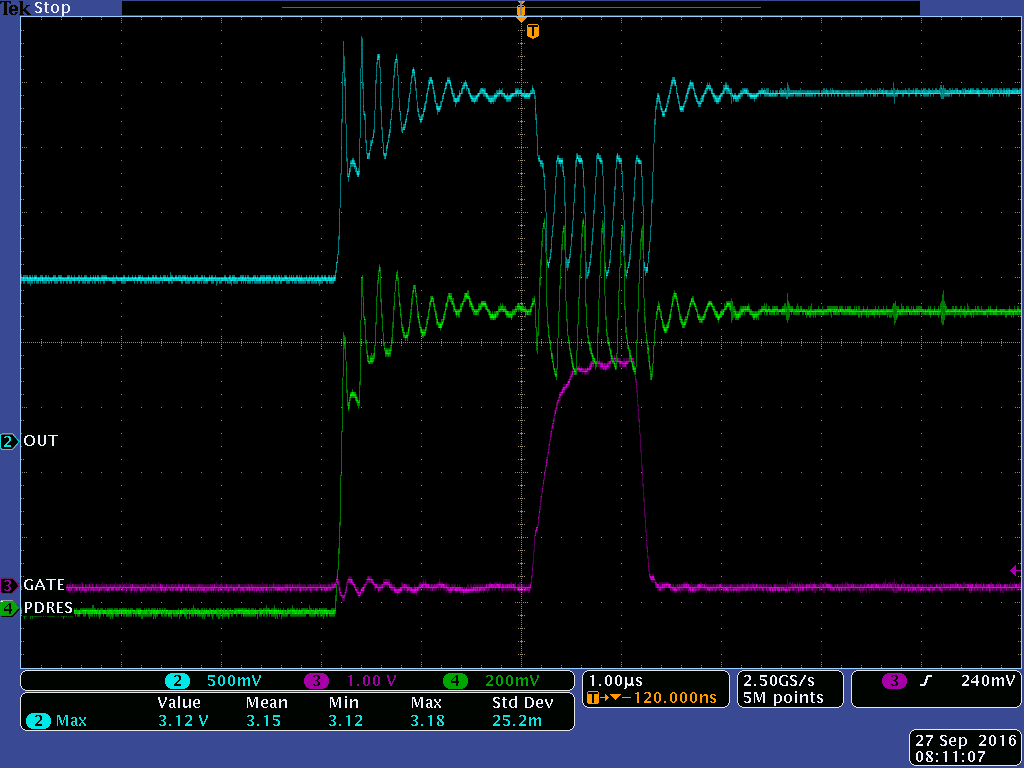
Referring to the below schematic, I am using a THS4531 to drive a laser diode (D5), whereby a photodiode is providing optical feedback current that is routing through a resistor (R18) to provide the feedback voltage. The reference voltage source is a PWM signal (TP50) passed through an LPF. When the low side switch (NMOS Q16) is active, the laser will turn on. I am observing an instability in the op-amp output shown in the following scope plot. The laser diode current is < 10 mA and the system supply voltage is +3.6 VDC (single supply). A 0.01 uF ceramic capacitor resides near the op amp between the supply and ground.

Op amp output: Blue; Photodiode return (TP49)n: Green; Q16 gate (TP48): magenta

Any insight as to what may be causing the undesired oscillations is appreciated.

-Andrew

  • Reposting since images did not appear:

    Referring to the below schematic, I am using a THS4531 to drive a laser diode (D5), whereby a photodiode is providing optical feedback current that is routing through a resistor (R18) to provide the feedback voltage. The reference voltage source is a PWM signal (TP50) passed through an LPF. When the low side switch (NMOS Q16) is active, the laser will turn on. I am observing an instability in the op-amp output shown in the following scope plot. The laser diode current is < 10 mA and the system supply voltage is +3.6 VDC (single supply). A 0.01 uF ceramic capacitor resides near the op amp between the supply and ground.

    Op amp output: Blue; Photodiode return (TP49)n: Green; Q16 gate (TP48): magenta

  • Hi Andrew,

    Can you provide more details on the laser diode and the photo diode?  Can you give me the capacitance and conversion ratio of the photo diode?  What is the forward voltage on the laser diode, and what is the power level?  Do you know for certain that the laser is turning on?  When the laser is off there is no feedback on this circuit and it will go open loop. 

    Also, I can't tell from the schematic, what is the votlage set for the Vocm pin of the THS4531?

    It does not appear that you are using one of the THS4531 outputs.  It also appears that there is no feedback circuit for the unused output. 

    Can you try placing a feedback resistor between Vout- and Vin+? 

    I will need some time to study this use case.  I'm not familiar with using a sense diode in a feedback loop, and I also don't have any experience with an FDA configured with only one feedback path. 

    Regards,

    Loren

  • Hi Loren,

    1. The laser diode has an integrated photodiode with a responsivity between 50 uA and 300 uA for a 5 mW laser radiant flux output. Unfortunately the photodiode capacitance is not specified by the manufacturer.

    2. The forward voltage of the laser diode at turn on is nominally 2.2 V. The diode is operating at 4.5 mW continuous wave.

    3. I can see the laser is turning on and from a visual perspective is operating correctly (the oscillations are far to fast to be observed with the unaided eye).

    4. I have tried placing a 1k resistor in parallel with the Q16 MOSFET to prevent the op amp from operating open loop when the MOSFET is off, but still observe the instability.

    5. I will try placing feedback on the unused output.

    Finally, the reason I am using this particular op amp for this circuit is due to its low current consumption. If you have other part recommendations that may be more suited to my application, I would be curious.

    -Andrew
  • Loren,

    The Vocm pin is floating.

    -Andrew