This thread has been locked.

If you have a related question, please click the "Ask a related question" button in the top right corner. The newly created question will be automatically linked to this question.

Video Signal negative part clipping

Other Parts Discussed in Thread: LM7171, TINA-TI

Hello All,

I am using LM7171 Voltage feedback amplifier to amplify 5MHz input signal using non inverting configuration.

Power supply for LM7171 is +/-12V.

After amplification, I get the output +/- 7V peak (+7 to -7), 5MHz amplified signal.

Up to here, it is working very good.

Now, I want to remove negative portion (0 to -7V) from this amplified signal. (i.e I want to clip negative part.)

For this, generally clipper circuits are used using diode & op amp.

My doubts are:

Can this clipper circuit perform this task for high frequency (5 MHz, +/- 7V peak) signal?

Diode(1N4148) used in clipper circuit able to handle such a high frequency signal?

Will output signal distorted in amplitude & frequency? 

Is there any other way to remove this negative part  without using clipper circuit?

Thanks in Advance.

Regards,

Jigar Patel

  • Hello,
    Can you attach your schematic please?

    Regards,
    Hooman
  • Negative_Clipper_Circuit.pdf

    Hi, Hooman

    Please check the above link for schematic.

    I am confused about output signal.

    will this negative clipper circuit so fast that it can handle 5Mhz,+/-7V input amplified signal?

    Will positive part of  output signal distorted due to diode speed limitation?

    Thanks,

    Jigar Patel

  • Hi Jigar,

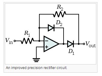
    Your circuit will cause the LM7171 output to saturate during the negative 1/2 portion of your input signal. instead, I recommend the "Improved Circuit" on the link below which avoids this output saturation instead:

    Since this is an inverting configuration, you may have to convert your front-end stage U1 to an inverting stage as well in order to get the correct polarity.

    Additional advantage of this circuit is that you are not operating the LM7171 with a closed loop gain (noise gain ) of +1 (it'd be a noise gain of 2V/V instead which is less "peaky" and better behaved).

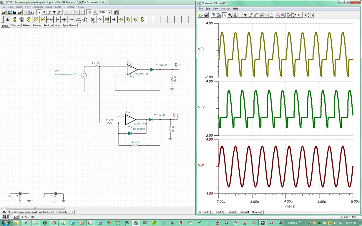
    The TINA-TI spike simulation does show that the diode turn-on / turn-off time causes a long tail during clipping. I've shown your original circuit and the modified version both next to each other. I've not experimented to see if a faster diode can help you here or not (I've attached the circuit so that you can experiment).

    LM7171 Negative Output Clipping E2E Hooman 11_28_16.TSC

    Regards,

    Hooman

  • Hi Hooman,

    First of all, thanks for your help.

    Now, i understand what was my mistake.

    Circuit that you have suggested is quite good, but i need one extra LM7171 opamp to invert my signal before giving it to clipper circuit.

    7446.Negative_Clipper_Circuit.pdf

    Kindly check above link. I have modified my schematic.

    In this, op amp will not be saturated; but i will get negative -0.7V max & positive signal.

    Now is there any way to remove this -0.7V?

    For high frequency signal, diode's capacitance  comes in picture. How can i calculate diode capacitance for 5MHz signal?

    Regards,

    Jigar Patel

  • Hi Jigar,

    One issue I see with the way you've used a diode after a series resistor (R5, 1k) is that you no longer have a "low impedance" output. If you plan to "drive" any load of significance, this high impedance would affect you. With the diode within the feedback, you avoid this issue. Of course the other advantage of using the diode within the feedback path is that you don't have the peski 0.7V diode drop to contend with!

    If you want the clamping to occur at 0V (and not -0.7V), you could possibly:

    1. Use a schottky diode (this reduces the "error" to about -0.2V instead of -0.7V for a PN junction diode like the 1N4148).

    2. Bias the diode Anode to a supply / source of -0.7V which you'd then have to generate. There are some switched cap sources that can do this (provided the current demand is not excessive). Here is a list of some of these products: 

    But you still have the issue of "high" impedance output I noted above.

    Regards,

    Hooman

  • Hi Jigar,
    You had also posed the following question I had forgotten to respond:
    "For high frequency signal, diode's capacitance comes in picture. How can i calculate diode capacitance for 5MHz signal?"

    The diode capacitance is a function of applied voltage and varies with the signal swing. The best way would be to use simulation to see the transient behavior, just like I had done with TINA-TI yesterday. The simulation models would be fairly accurate for such behavior.

    Regards,
    Hooman
  • Hi Hooman,

    In my modified circuit,

    I have to use one voltage follower after clipping circuit & circuit design to remove -0.7V.

    The circuit that you have suggested has advantage of low impedance output.

    So, I will go for the circuit that you have suggested. 

    Thanks for your guidance.

    Regards,

    Jigar