This thread has been locked.

If you have a related question, please click the "Ask a related question" button in the top right corner. The newly created question will be automatically linked to this question.

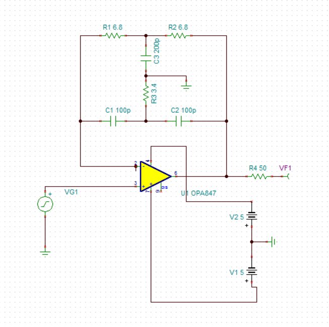
OPA847 with a special feedback net,TINA stable, but it Oscillations

Other Parts Discussed in Thread: OPA847

Dear TI :

I am  trying to implement a circuit as shown

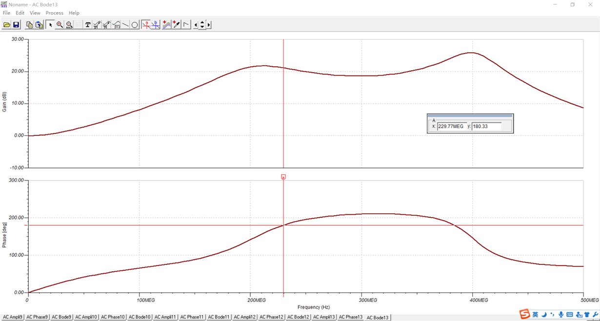
 the following Bode plots

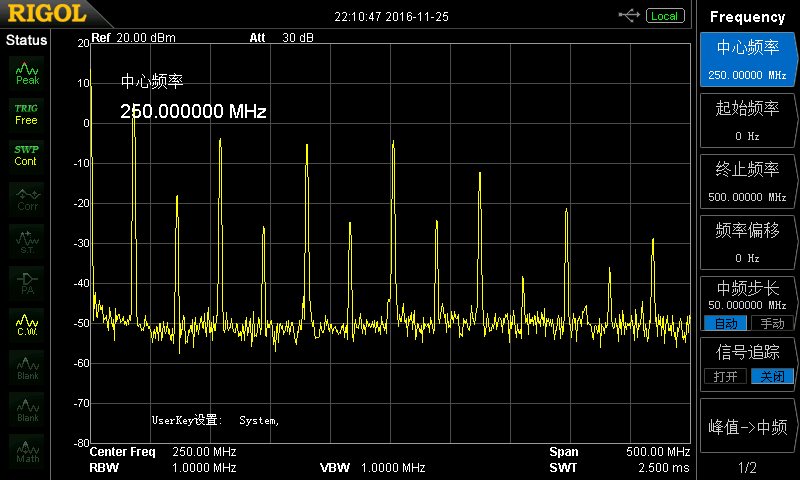
I made a PCB, and choose the component as simulated circuit, but the oscillations phenomena appears without input.

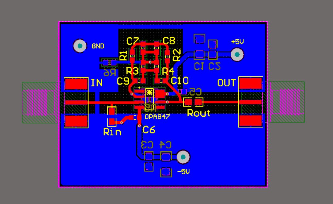
this is my PCB layout and screenshot of spectrum analyzer

I want to know why the  oscillations phenomena appeared and how can get the result as Bode plots of the simulation .

thank you very much

  • Hi Xin,

    The circuit you have designed using the OPA847 is inherently unstable.

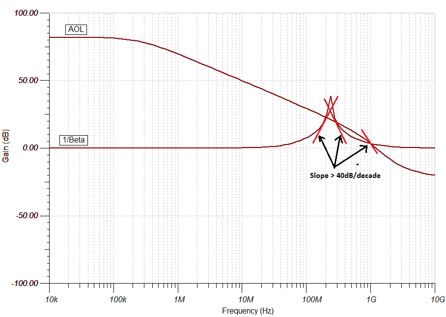
    The OPA847 is stable for gains greater than or equal to 12V/V. Since, the circuit you have developed is unity gain, you will have excess phase shift (>180') at the frequency where the open loop gain intersects with the noise gain of the circuit leading to oscillations. If you look at the intersection of noise gain (1/Beta) and the open loop curve of your circuit, there are three potential points of oscillation (as shown below) where their slope of intersection is greater than or equal to 40dB/decade (or exhibits > 180' phase shift).  

    Are you trying to achieve some sort of band-pass filter with the circuit? There should be a simpler circuit than this for what you are trying to do. It would be better if you could describe in detail what you are trying to achieve in-order for me to help you further.

    Best Regards,

    Rohit

  • Dear Rohit,

             Thank you very much for your reply. I really appreciate it.

             As you see from the Bode plots, I want to implement a circuit with the function: In the range of 1MHz to 200MHz, with the frequency increased, the gain increased, too. And the gain of low frequency still above 0dB.

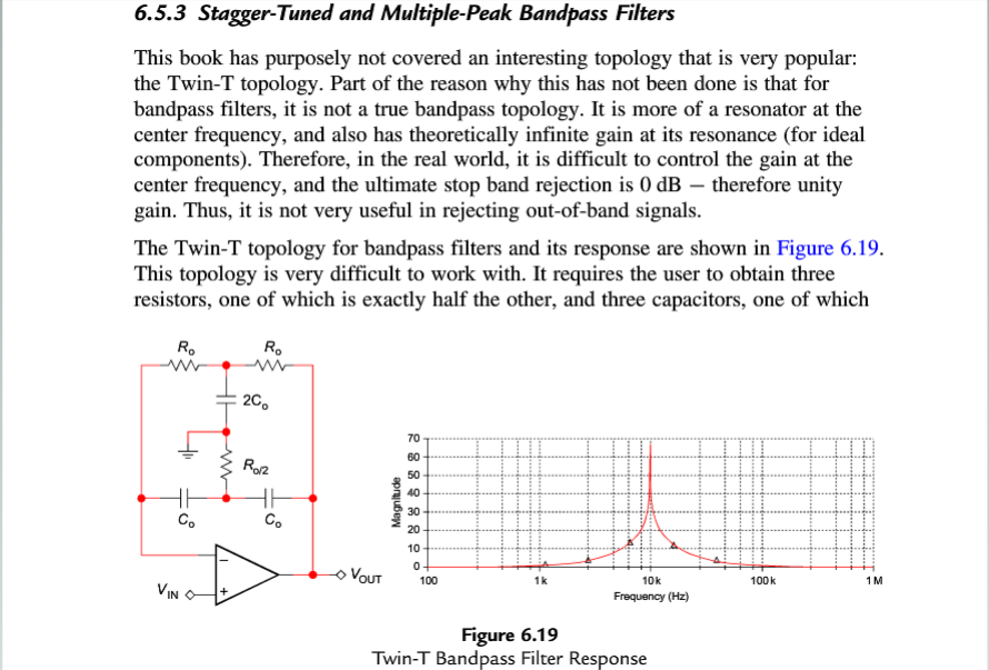
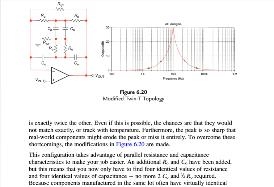
    I fund the circuit on "Op Amps for Everyone,4E"(written by Bruce Carter),on the charter6, This meets my requirements

    So I made a simulation on TINA, and set the values of R and C to make a peak gain on 200MHz. then make a pcb, and Oscillations.

    if you can give me a another circuit which can achieve it.  I would be very grateful to you.