This thread has been locked.

If you have a related question, please click the "Ask a related question" button in the top right corner. The newly created question will be automatically linked to this question.

High bandwidth (over 30MHz) current source/LED driver circuit

Other Parts Discussed in Thread: LM6171, LMH6629, LMH6702, LMH6703

Hi everyone,

I am looking to design an analogue voltage controlled votlage source with a bandwidth of over 30MHz. I am considering the usual op-amp plus transistor configuration. I am not so sure wether a MOSFET or BJT is the best option. I am planning to connect 2,3, or 4 transistors in paralled to be able to achieve the desired level of current and alos minimise the power dissipated in each transistor.

Can anyone help with suitable components please.

Thank you.


Wasiu


  • It would be important to see the schematic of your circuit.  There are many problems designing such a circuit.  Some (most) topologies have a relationship between the impedance of the load and the bandwidth of the control loop.  Also high speed opamps are sensitive to both signal amplitude and load capacitance.

    A Mosfet likely has way too much capacitance, unless it is a mirowave (LDMOS) FET, which are quite expensive.  Small VHF transistors may work, but again the capacitance is likely a killer.  Paralleling devices is not going to work well, especially with FETS, since they will oscillate amongst each other unless you have  a gate resistor, which would then kill the bandwidth.

    How much current do you need?  Do you have a good 30MHz model for he LED?  If you can post a schematic I will see if I can offer some suggestions


    Regards,


    steve

  • Hi Steve,

    The schematic is shown below. 200 -500mA will do fine. I am thinking of RF NPN transistor with very wideband voltage feedback op-amps.

    I initially used LM6171 op-amp with 2SC5707 transistor on a prototype board (Not full PCB, connections made with copper wires soldered to leads) but the circuit had huge 'peaking' just under 10MHz. I am therefore thinking of using proper PCB board.

    Any thoughts?

    Many thanks

    Popoola


  • 1781.CurrentSource.pdf


    Hi Steve,

    The schematic is shown below. 200 -500mA will do fine. I am thinking of RF NPN transistor with very wideband voltage feedback op-amps.

    I initially used LM6171 op-amp with 2SC5707 transistor on a prototype board (Not full PCB, connections made with copper wires soldered to leads) but the circuit had huge 'peaking' just under 10MHz. I am therefore thinking of using proper PCB board.

    Any thoughts?

    Many thanks

    Popoola


  • The large peaking means that the bandwidth is 10MHz and the phase margin is terrible.  High Speed video amps do need a proper PCB with a good ground plane, but that is not the issue here.  There are several problems

    1) Not all amplfiiers are unity gain stable.  This circuit requires a unity gain stable amplifier

    2) the capacitance of the three parallel transistors will be pretty high.  That can significantly impact the performance.  You will need a series resistor between the amp and the transistors.  The value is dependent on the amplifier and the capacitance of the transistors

    3) At high frequencies, the wires to the LED are inductive.  THis inductance needs to be countered, by a series RC from te collector of the transistors to ground.


    I hope this helps


    Steve

  • Hi to all,

    I want a circuit with 3-dB level BW of 400MHz and higher.

    I tried to simulate (SPICE) a simple combination of actual single OpAmps and P-Ch MOSFETS

    and could get maximum 235MHz of OpAmp LMH6629 & MOSFET at 100mA output level.

    Can some one advise a transitor (or both components, or a schematic) that can give desired BW?

    Thanks. marco


  • Hi,

    LMH6629 is probably not a good choice for this application as it is not unity gain stable. One possibility is to use a high speed current feedback amplifier like LMH6702 (or LMH6703) as the active element and use a 240ohm resistor between the Emitter and the inverting input of the op amp (suggested RF value in datasheet). Simulation shows in excess of 500MHz of speed. If you use a resistor in series with the transistor base, you could possibly parallel it with some capacitance and use that to tune your response.

    From your description, unity gain with 200-500mA output current, all you are asking for is a high speed buffer. Stand alone buffers are available with those specifications: Here are some buffers from the original National website and TI websites:

    http://www.national.com/cat/index.cgi?i=i//15

    http://focus.ti.com/paramsearch/docs/parametricsearch.tsp?family=analog&familyId=2116&uiTemplateId=NODE_STRY_PGE_T&paramCriteria=no

    Hope this helps.

    Hooman

  • Hi,

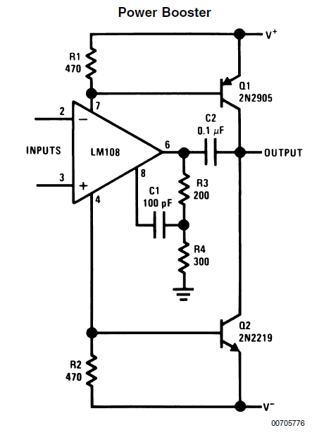
    I've attached a scheme from AN-31 which uses external BJTs with their Base drive from the sensed supply current of the active device (LM108). LM108 can be replaced with a high speed, modern device for testing. This probably won't get you to the 400MHz you are looking for, but it might be worth looking into.

    Thanks,

    Hooman

  • Hi Hooman,

    Thank you for your replys that I just found here. I will look tomorrow morning on them.


    Here is the current source circuit that i am trying to simulate/modify,

    OpAmp was TLV245XA (Rail-to-Rail), P-ch-MOSFET NTHD5903.

     it gives 250mA.  It is a part of larger schema,

    There are few such similar circuits, for different discrete values of output currents from 15 mA to 250mA 

    that is why there are some limitations:

    1.) Single polarity dc supply of fixed value 2.9V.

    2.) I need Spice models for both Op Amp and transitor(s) for further simulations,

    Do you have models for LMH6702(3)?

    plz help

  • Hi,

    For models just visit the web site:

    http://www.national.com/assets/en/tools/spice/LMH6702.zip

    http://www.national.com/assets/en/tools/spice/LMH6703T.zip

    Thanks,

    Hooman