This thread has been locked.

If you have a related question, please click the "Ask a related question" button in the top right corner. The newly created question will be automatically linked to this question.

THS4521: Signal from sensor dies out when connected to THS4521 amplifier circuit

Part Number: THS4521
Other Parts Discussed in Thread: THS4551, TINA-TI, OPA365

I would like to amplify a low frequency signal of about 100-2000Hz that ranges from -100 mV to 100mV upto about -3 V to 3 V. When I use the THS4521 amplifier to amplify a toy signal from a wave generator it amplifies properly however when I connect my actual sensor to the amplifier circuit all of the input signal just dies out. I have checked the sensor and it is working appropriately by itself so there must be some issue with its interaction with the amplifier circuit. Would appreciate help regarding any possible solutions or ways to debug this problem. 

  • Hello Zain,
    It is possible that the sensor cannot drive the current required by the THS4521. Can you please attach your circuit schematic as well as the type of sensor you are using.
    Also, we have an upgraded lower noise, higher precision version of the THS4521...please look at the THS4551.
    -Samir
  • Hi Samir,

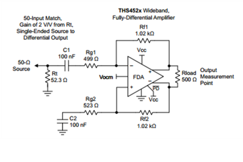
    Sorry for the late reply. I have attached a picture of my circuit below (I have ac-coupled the sensor) and I am trying to amplify signals from a piezo film sensor. The initial problem was that when I was attaching the sensor to the amp. the signal from the amplifier was just dying out (the signal was fine when I detached it from the amp and checked the sensor alone). I have fixed this problem by ac-coupling and putting a very high value resister at Rt, however now I get nothing at either of the differential outputs. Can you please advise how I can approach the problem. 

    Values used for the circuit below are: Rf1 = Rf2 = 1kOhm, Rg1 = Rg2 = 220 Ohm, C1 = C2 = 100nF, Rt = 3kOhm (For a low value of Rt about 50 Ohm the input from the sensor dies out giving the same problem as before)

  • Hello Zain, try removing Rt and testing it.

    What is the frequency of your input signal? Can you please simulate your circuit in TINA to make sure your ac capacitors are low impedance in the frequency of interest? Also,

    1. How much power is the device consuming?

    2. What are the power supplies set at?

    3. What is Vocm set at or is it left floating (floating is okay, as there are internal resistors that bias it to mid-supply)?

    4. What is each output of the amplifier measuring?

    5. Please ensure PD is tied high.

    -Samir

  • Hi Samir,

    The signal I am trying to amplify ranges from 50-2000Hz. I am providing the sensor with 5V and the amplifier circuit rails at +5V and Gnd.

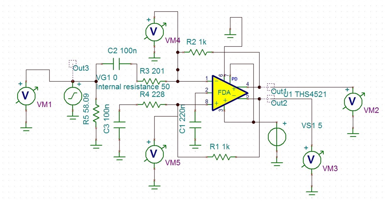
    I have simulated the circuit in TINA and have an idea as to what might be causing the input from the sensor to die out. Have a look at the circuit diagram in TINA and two simulation results from TINA.

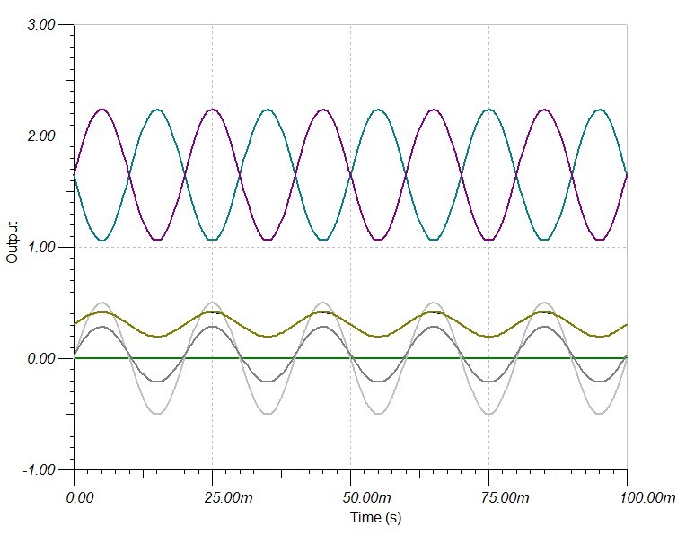
    This is the output for the simulation assuming the sensor internal impedance(labelled Internal resistance in the above schematic) is low at about 50 Ohms. Where the cyan and purple waveforms are the two differential outputs VM2 and VM3. And the olive coloured signal is the dc biased input signal to the amplifier. As you can see below the input signal is not squished and the output correct. 

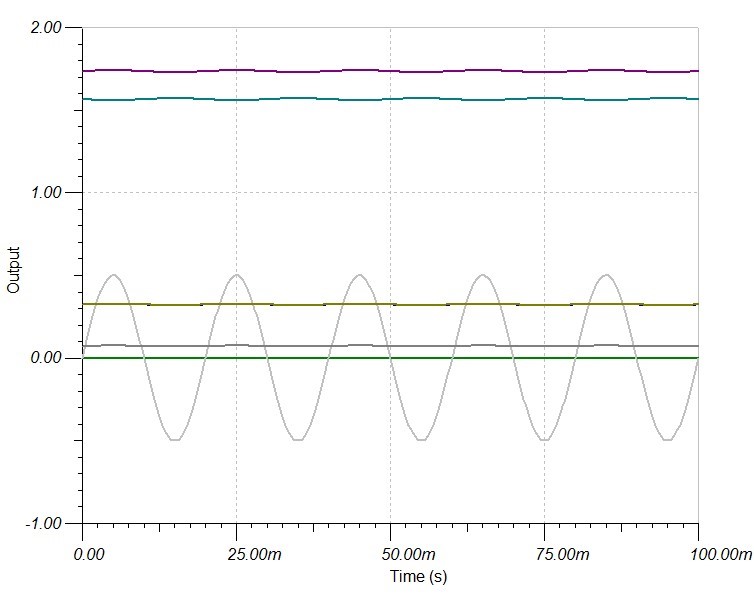
    However now if we put a very high internal impedance for the sensor at about Internal resistance = 10kOhm and run the simulation again you can see that the input signal provided to the amplifier is squished and the outputs are amplified but also squished.:

    Do you know how we can amplify the signal from a high impedance voltage sensor?

    Thanks

    -Zain 

  • Hi Zain,

    I would not recommend using the 100nF ac coupling capacitor, as it will attenuate the signal frequency in the range of 50-2kHz. Based on what you are describing, it seems like you would need a high input impedance amplifier on the range of 10kohm or higher to amplify the signal from a high impedance voltage sensor. Here are two suggestions that you could try:

    1. You could try to increase the input impedance of the THS4521 using the Circuit 1 below and see if the output signal is restored. In the below Circuit 1, I have used a feedback capacitor of 2pF across the 50kohm feedback resistor for stability purposes. You might have to tweak that depending upon the input parasitic seen across the Rg resistors on your board. One thing you need to be careful is to provide the same DC bias voltage on the un-driven side of the FDA as that available from the voltage sensor, so as to not have a large DC offset at the FDA outputs. I have attached the TINA-TI schematic for the same: THS4521_HighImp_Sensor.TSC

    Circuit 1:


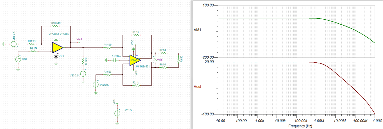
    2. You could use a high impedance JFET/CMOS input op-amp like the OPA365 to buffer the voltage sensor output before applying it to the THS4521 FDA (Circuit 2). Here as well, the DC voltage on the -ve input of the OPA365 should be similar to the one available from the voltage sensor for proper single +5V operation. The TINA-TI circuit is attached: OPA365+THS4521_HighImpVoltageSensor.TSC

    Circuit 2:


    Let me know if this works.

    Best Regards,

    Rohit