This thread has been locked.

If you have a related question, please click the "Ask a related question" button in the top right corner. The newly created question will be automatically linked to this question.

Could you recommend some op-amps suitable for DCR sensing application?

Other Parts Discussed in Thread: OPA2822, THS4222, LMH6654, LMH6626, THS4031, TINA-TI, THS4631, OPA2354, LMH6619, OPA2890, THS4221

Hi friends:

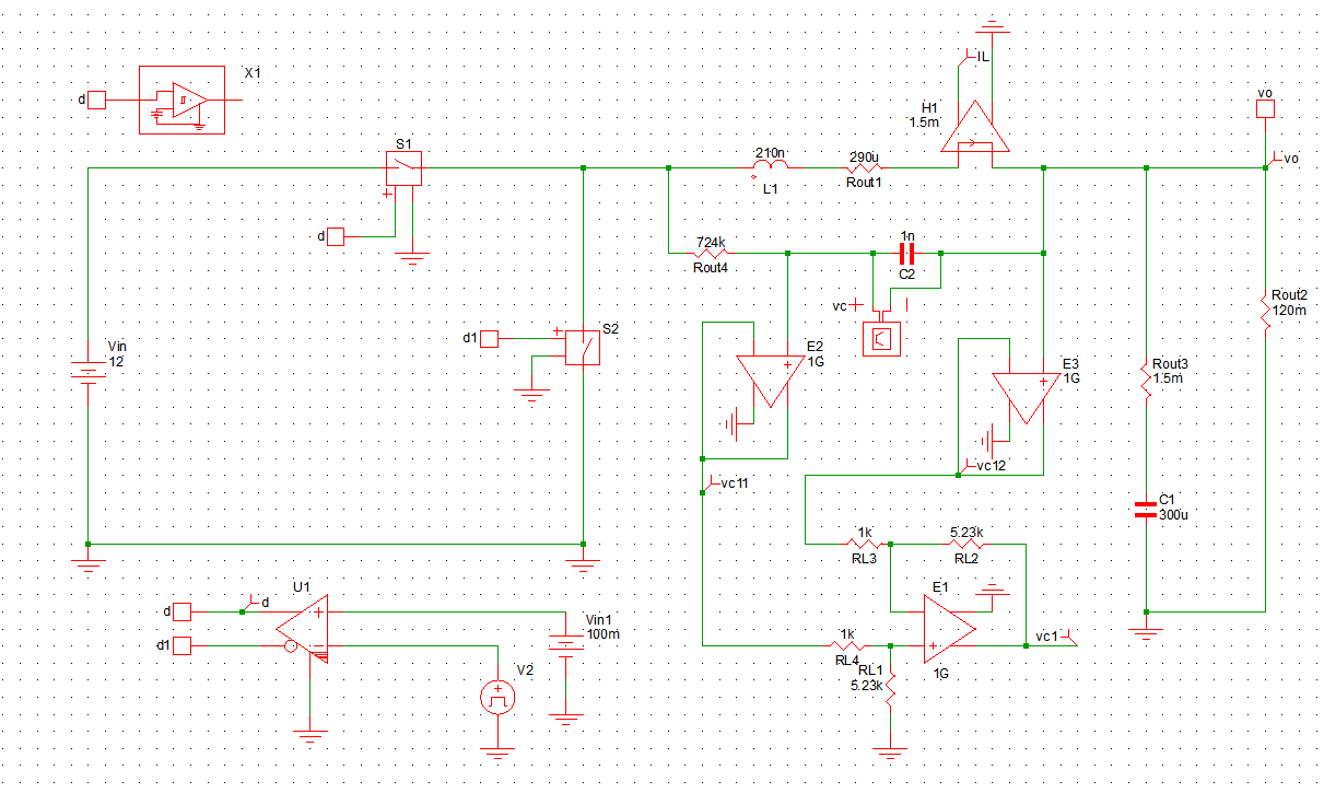
        I need some amplifier to build up the signal modulation for the DCR sensing for the VR application. In my application, the power supply  can be -5V/0V/+5V . There are two phase interleaved. The switching frequency is 1MHz. The sensing current for each phase is 5A to 30A. And the equivalent sensing resistor is 1.5m ohms.

First, I need  two amplifier work as the buffer to sense the inductance voltage of each side for each phase. Then need one amplifier work as the differential amplifier and summing amplifier.

At first, I selected several op-amps for usage. Such as THS4222, LMH6626,LMH6654,OPA2822 and so on.

However, by simulating their SPice Model. Some chips seem not to work well, such like OPA2822 and LMH6626. For LMH6654, I cannot find the SPice Model.

Could you recommend some popular chips which can be used in this application? 

Best wishes,

Lucy

  • Hello Lucy,

    We are currently out of the office, we will get back to you when we return on Monday
  • Hi Luxing,

    Could you please attach the SPICE/TINA-TI simulation circuit for the application you are trying to implement? Two other parts you can use for this application are the THS4631 and THS4031.

    Best Regards,

    Rohit

  • Hi Rohit,

     thanks for your reply.

    I only simulate it in the SIMtrix with the model downloaded from our website, and the format is XXX. sxsch, which cannot be attached in this letter. Could you tell me your email address? I can send the simulation files to you by email.

    In addition, the chips you recommend have a large power supply. Do we have some chips with -/+5V as typical power supply?

    I am looking forward to your reply. 

    Best wishes

    Lucy

  • Hi Luxing,

    Could it be possible for you to attach a screen-grab of the circuit? I don't think I have SIMtrix to simulate the model if it is available in XXX.sxsch format. Can you use TINA-TI for your simulation instead?

    I think the THS4222, LMH6654 and OPA2822 parts you have selected should be good for 1MHz frequency +/-5V supply operation.

    Best Regards,
    Rohit
  • Hi Rohit,

    This is the circuit I build in the simplis.

    It is a ideal buck with DCR sensing, where E2 and E3 are the buffers and E1 works as the differential amplifier.

    I simulate the real model of THS4222, OPA2822, OPA2354 and LMH6626 and so on. It turned out OPA2822 and LMH6626 cannot work as E2 and E3. Finally, I use OPA2354 as E2 and THS4222 as E1. However, in the experiment, I notice several phenomenon.

    First, THS4222 operates at a high temperature of 60 degree centigrade. However, the voltage it deals with only tens mv to hundred mv, which is quite small. What is the reason?

    Second, the signal after these chips have a large pick at the rising and falling edge of the duty cycle signal. I worry whether the bandwidth of these chips quite large, which is not suitable for my application. Generally, for the 1MHz operating case. What is the recommending  bandwidth of the chips should be applied? 

    I just want to choose a suitable chips which can be applied in my application. I am looking forward to your reply.

    Best wishes,

    Lucy

  • Hi Lucy,

    1. If the THS4222 chip operates at a high temperature of 60 degrees, then it could be that the part is oscillating. Have you looked at the THS4222 output to see if there is an oscillating sine wave?

    2. It is possible that the large pick at the rising and falling edge of the duty cycle signal is due to the high frequency peaking (which could be causing the instability). For your application with 1MHz operating case, you would normally need a >50MHz bandwidth that is unity gain stable for E2 and E3. You can use the OPA2890/LMH6619 at the E2 and E3 for your application. I think the THS4221/THS4222 should be appropriate as the E1.

    Best Regards,
    Rohit
  • Hi Rohit, 
         Thanks for your reply. I want to show you the comparison between the simulation and some experimental waveform in my application.

    figure 1 shows the basic connection in my application. However, the buck in simulation is the equivalent buck circuit without closed loop control.

    figure1

    figure 2 shows the waveform of Vo, Vo1 and switching note.

    figure 2     

    Figure 3 shows according experimental result in the steady state condition. Yellow line refers to the AC component of vo. Blue line refer to Vo1, which is the difference between Vc and current signal. Green line refers to the switching node voltage. The sequence is the same with that in figure 2. from figure 3, it can be seen the peak voltage at vo1, which is not in the simulation part.

    figure 3

    However, when increase the switching frequency to 315kHz, re-look the waveform under the steady state condition. figure 4 shows the simulation waveform and figure 5 shows the experimental result. 

    figure 4

    figure 5

    It can be seen the peak voltage on Vo1 in the experimental result becomes much larger, the shape of which is apparently distorted compared with that in the simulation waveform.

    Question: (1) Does the peak voltage on Vo1 in figure 5 refer to the oscillating for THS4222? (2) Where does it come from and how to solve it? (3) Why in the simulation, the real model can work well?

    I am looking forward to your reply.

    Best wishes,

    Luxing

  • Hi Luxing,

    1. It does not seem that the peak voltage on Vo1 in Figure 5 refers to an oscillation caused by THS4222. For an oscillation, usually you expect the same kind of waveform riding on a DC voltage irrespective of the switching frequency.

    2. It could be a possibility that the issue is related to the phase difference between signals that arrive at different times at the difference amplifier inputs, which leaves a common mode signal at its output. I think this can be mildly seen on Figure 3 as well. I would recommend probing the U1 and U2 outputs to see whether the signals arriving at the difference amplifier input X8 are in the right phase. The same can be thought of the Vo1 difference amplifier inputs at X2 that subtracts the VL11 and VL12 signal paths. The other possibility could be settling of the 12V square wave at the U2 output which is causing the difference in voltages in experiment compared to simulation. Do you know what is the rise time of the 12V square wave?

    3. As mentioned in (2), I don't think the real model captures the subtle difference in phase that causes the issue you are noticing. You might be able to introduce some delay between the inputs to the difference amplifier in the simulator and see whether it reflects what you are seeing in experiment. Also, do you know whether the input to U1 is around 12V? If it is, then I think you might be violating the input common mode voltage of the OPA2354. This is because the OPA2354 is only operated on a single 5V supply.

    Best Regards,

    Rohit