This thread has been locked.

If you have a related question, please click the "Ask a related question" button in the top right corner. The newly created question will be automatically linked to this question.

THS4222: High failure, chip not working

Part Number: THS4222
Other Parts Discussed in Thread: THS4522, TINA-TI, THS4524

Hi,

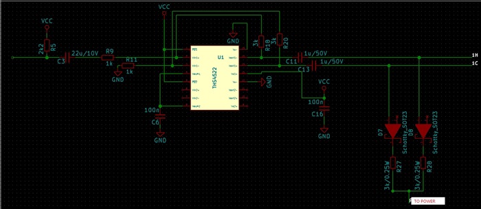
I have a big problems with THS4522. I got samples and used it in our project. You can see part of design in the attachment. The problem is after soldering, some chips doesn't work - it looks like they are broken. Some of them works for a while, but after that they crashed. We don't know what is going on with these chips. Can anyone help?
  • Hi Mateusz,

    I think you need a 22uF cap between the R11 and GND on the Vin1- input side. This cap is required to balance out the differential inputs. Without this cap, you will see a huge offset at the outputs which will cause the device to not work reliably.

    Best Regards,

    Rohit

  • Hi Rohit,

    Thank you very much for reply. It seems that with that capacitor design will be better, but I am wondering if that will stop chip damage? I don't know if it is problem with design or failed chips? Almost is damaged now.

  • Hi Matuesz,

    I would recommend to simulate your circuit in TINA-TI to better understand whether the design has a problem. You might want to simulate with the actual output load and do ac analysis to make sure there are no oscillations in your design.

    Without the 22uF cap between the R11 and GND on the Vin1- input side, you are introducing an asymmetry in the differential inputs.  As a result, one of outputs is railed with a huge offset and the device stops working. I think that might be what you are seeing in your setup.

    I have attached the TINA-TI circuit if you want to take a look. sboma73a.TSC

    Best Regards,

    Rohit

  • Hi Rohit,

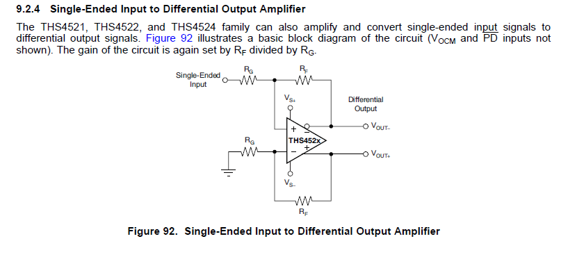
    Thank you for reply. I made a simulation in LTSpice also and now i see the offset (earlier i check it after capacitors on output lines so i didn't see DC offset). The problem is this design is in Texas Instruments datasheet. Can anyone explain that?

  • Hi Mateusz,

    The circuit you have attached above is for DC-coupled application where it is assumed the single-ended input is GND referenced.

    I would recommend you to go over Section 8.4 in the datasheet for information on the AC and DC coupled single-to-diff signal path.

    Best Regards,
    Rohit
  • Thank you for the reply,

    I use electret microphone as input.

    I read documentation and power consumption should be about 1mA per channel, but my design take about 30mA. Am I doing something wrong?

  • Hi Mateusz,

    I don't think the power consumption should be 30mA, as it is way too high for this part. Have you added a cap between the R11 and GND in your circuit to make sure your circuit is AC coupled for both the THS4522 inputs? Is there any other circuit (a resistor to GND) that could be drawing the additional current?

    If not, then it is possible that the part could be damaged and I would recommend to replace the device and make sure the current reading is right.

    Best Regards,
    Rohit
  • Hi,

    I used THS4524. After changes you mentioned new pcb are still broken. I will send you full design in private message, but you can answer here so maybe it will help other users :)
  • Hi Mateusz,

    Please send the full design file so that I can look over.

    Best Regards,
    Rohit