This thread has been locked.

If you have a related question, please click the "Ask a related question" button in the top right corner. The newly created question will be automatically linked to this question.

THS4121: THS4121 TINA circuit question

Part Number: THS4121
Other Parts Discussed in Thread: TINA-TI, LMH5401, OPA847

Hi team,

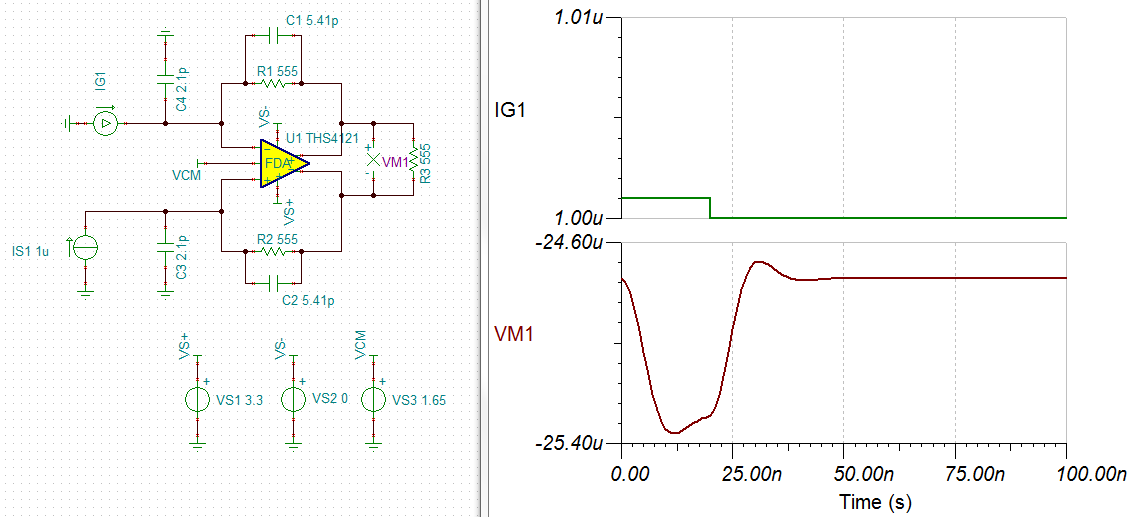
The customer designs a TINA circuit for THS4121. For his simulation circuit, it exists the shock. 

For more detail information, please check the attachment. 

Is the customer's  simulation circuit and the  simulation result correct? 

If it is correct, would you suggest how to solve the shock issue? 

If it is incorrect,  would you send me a correct simulation circuit for the customer's application?

THS4121.docx

Best Wishes,
Mickey Zhang
Asia Customer Support Center
Texas Instruments

  • Hi Mickey,

    I verified the simulation circuit as attached in the word document and don't seem to see any oscillations in the waveform.

    Attached is the TINA-TI file for the same: THS4121_TIA.TSC

    One thing I noticed is that the customer could look into using a low-noise front-end such as the OPA847 that performs the trans-impedance (TIA) operation and follow it up using the LMH5401 for the single-ended to differential conversion. This way the signal chain could have more gain to process the pulse at the detector input.

    Best Regards,

    Rohit

  • Hi Rohit,

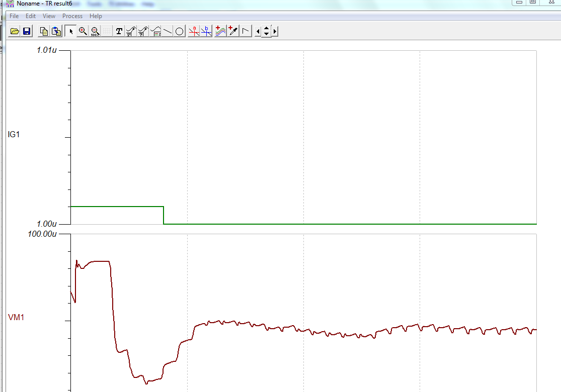
    Thanks for your support. The customer select "Zero initial values" for transient analysis. 

    I use the Tina file that you send to do the  transient analysis and select  "Zero initial values". 

    Then the simulation result exist the oscillations. Please check the attach. 

    If the customer select  "Zero initial values" for transient analysis, does the circuit exist the oscillations? 

    If it happens the oscillations as the customer described in the actual circuit, how to solve the oscillations issue?

    If THS4121 is not suitable the customer's application, can OPA847 and LMH5401 achieve the customer's application?

    If they can, would you send me a TINA circuit?

  • Hi Rohit,

    Do you have any suggestions? The customer is waiting for my reply.
  • Hi Mickey,

    I would not recommend using the "Zero Initial Values" for transient analysis as it gives unexpected results with an unknown operating point, which has been noted in the attached waveform. I would stick with the "Calculate Operating Point" for transient analysis because it converges the simulation to a known operating point.

    Do you know what photo-diode part number is the customer using? Also, is the requirement to only amplify a 1nA input current? If the input current requirement is true, the customer would need a very high transimpedance (TIA) gain stage input to bring the output signal close to any detectable output signal levels. This will substantially reduce the TIA BW, which may not allow detection at very short pulse durations.

    Best Regards,
    Rohit