


Hello,
I need some help with the behavior of the spice model for OPA657 opamp. I'm simulating a transimpedance amplifier with the OPA657 but I found a diference in the behavior depending on which revision I use.
I tested with the following two macro models (I transcribe only Headers of .sub files):
Model (1)
* OPA657 Non-Unity Gain Stable, FET Voltage Limiting Amplifier
* REV. A - Created 1/21/02 Rea Schmid
* REV. B - Created 2/26/02 Rea Schmid - Purpose to adjust voltage and noise curves
Model (2)
* OPA657 Non-Unity Gain Stable, FET Voltage Limiting Amplifier
* REV. A - Created 1/21/02 Rea Schmid
* REV. B - Created 2/26/02 Rea Schmid - Purpose to adjust voltage and noise curves
* REV. C - Created 6/27/06 Xavier Ramus - to correct input stage oscillation
* REV. D - Created 10/23/06 Xavier Ramus - To correct Noise
* REV. E - Created 11/22/06 Xavier Ramus - To correct behavior in transimpedance applications
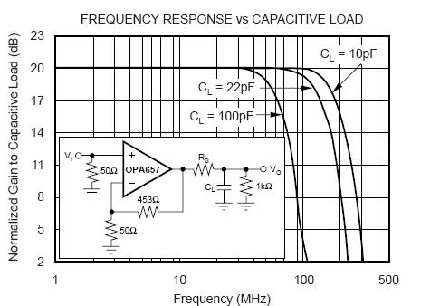
The model (1) Is included in TINA software and model (2) was downloaded from TI webpage. I'm sure I should use model (2) because the REV.E. But as I had some doubts about the behavior, I tested the circuit of page 7 of the datasheet (Frequency response vs capacitive load).
I obtained a very acceptable simulation result with model (1), but an unclear result with model (2). I use the same circuit, even the same file. I only change the component macro model.
Simulation obtained with model (1)

Simulation obtained with model (2)

I would really appreciate if you can help me and tell me about what is going on and explain me about these behavior differences. I'm designing a transimpedance amplifier with BW=20MHz and I'm trying to have an improved simulation to compare the PCB behavior vs the simulation.
Thanks a lot in advance
Gaston


