This thread has been locked.

If you have a related question, please click the "Ask a related question" button in the top right corner. The newly created question will be automatically linked to this question.

THS7002EVM: Impedance Matching

Part Number: THS7002EVM

Hi. I recently bought a THS7002EVM. I plan to use this to interface it to the function output of an oscilloscope, so I can get a higher voltage than what the oscilloscope can yield (0-2 V). The problem I'm having is that the function output of the scope has a 600 ohms impedance, while the input impedance to the THS7002 EVM is 50 ohms on both input channels. Is there any change that can be done against the THS7002EVM to ensure there's no signal loss why coupling the scope to this board ?


Regards,
Mihai

  • Hi Mihai,

    if it was my eval board I would remove R9 and R16 from the eval board and replace them by 470R resistors. If using an as short as possible connection between the function output of the scope and the eval board input, this could work. But I don't want to recommend you to do this! Because if you make a soldering mistake the board is damaged.

    A better method would be to spend the function output an additional 50R unity gain buffer which is able to feed the 50R input impedance of eval board. Or you could cascade two eval boards...

    Kai

  • Hi Kai,

    I'd rather avoid replacing the resistors, specifically since I don't own - at least yet - the tools needed to operate against SMD components. Regarding the 50R unity gain buffer - do you mean adding something like the reply from user helloworld922 on this thread ? Would this be located between the function generator output and the evaluation board itself ? If so - wouldn't the problem be "moved" further "back" between the function output and the unity gain buffer ? Or it wouldn't matter since the current inside the op amp's inputs is too low ?

    Not sure I follow the idea of cascading 2 boards. How would this fix the problem ?

    PS Sorry about the insufficient knowledge level on my side, I'm trying to get up to speed and remember theoretical information learnt in college more than 10 years ago.

    Regards,

    Mihai

  • Hi Mihai,

    unfortunately, I cannot open your link given in your last post.

    Yes, such a buffer would be placed between the function generator output and the eval board. It would have an input impedance of let's say 600R, which is much higher compared to 50R. This would dampen the signal of function generator only by a factor of two. The buffer would have a gain of 1 (or even 2, to compensate for the dampening) and would have an output impedance of 50R. This output could be connected to the 50R input of eval board by using well known 50R technique.

    50R technique means, that you have a driver with 50R output impedance, a 50R cable and a receiver with 50R input impedance. 50R technique is usually used for high frequency signals to avoid signal reflections, dampening by cable capacitances, etc. Without 50R technique you cannot connect two devices by a cable carring a high frequency signal. That's the reason why the eval board has 50R inputs.

    In your case the function generator has an output impedance of 600R, indicating that the signals are not of very high frequency. So, you would not urgently need 50R technique.

    How would cascading of two eval boards fix the problem? If you cannot change the input impedance of eval board and you still want to use this eval board, then you must accept a signal dampening of about 22dB. Right? When you cascade two eval boards you would achieve a gain of 2 x 20dB. So, you would end up with a total gain of 40dB - 22dB = 18dB, when cascading two eval boards.

    Kai
  • Hi Kai,

    I've fixed the link in my previous message.

    Like you very well pointed out, the function generator has a maximum frequency of only 1 MHz.

    Considering the case of just one eval board connected directly to the function output. If ZL=50R and ZS=600R, this would yield a reflection coefficient (gamma) of (ZL-ZS)/(ZL+ZS) = -0.846. The mismatch loss then is -10*log10(1-gamma^2)= -10*log10(1-0.716)= -10*log10(0.284)= -5.4 dB. However you mention that the signal dampening will be 22 dB. There's probably something wrong with my calculation, but can't figure out what.

    My concern - not sure if valid though - is that through impedance mismatching I'll also be losing part of the 3rd, 5th, 7th harmonics, which would cause the a square wave that I'm outputting from the function generator to not be so "sharp" anymore.


    Regards,
    Mihai
  • Hi Mihai,

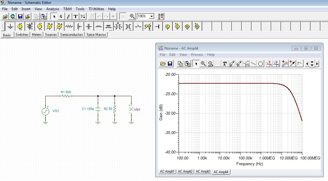
    I have simulated the dampening with TINA-TI for you:

    This simulation assumes a cable capacitance of 100pF. Coax cable RG 58 C/U has about 100pF per Meter. Corner frequency (-3dB decrease) of low pass filtering is at about 35MHz. With a much shorter cable the low pass filtering is even much smaller. 20pF cable capacitance (20cm cable) would result in a corner frequency of 173MHz.

    Kai

  • Hi Kai,

    Thank you for the link - the software is really nice, and the value of approx. -22 dB does make sense and it's verified if I analyze the simple circuit as a voltage divider.

    What I wanted to see was how the THS7002EVM behaves, specifically 2 instances connected together so that the overall gain is 40 dB. However I could only find the THS7002 symbol that can be added in TINA-TI. Do you think the noise picked up using the 2 eval boards would result in a too much distorted signal compared to the original input coming from the scope's function generator ?

    Regards,

    Mihai

  • Regarding the R9 and R16 resistors - would simply removing them, and not putting any other resistors in place, lead to a better outcome from the point of attenuation ? The voltage divider - formed by the scope's function generator 600R output impedance and the eval board input resistors - wouldn't be present any more, so the input into the eval board should follow closely the scope's function generator output.

    Regards,
    Mihai
  • Hi Mihai,

    correct! You can also remove R9 and R16, without replacing them with other resistors. But put the eval board close to the function generator. Then it should work.

    To remove a resistor from the board, put enough solder tin onto the tip of soldering iron and touch the resistor with the tip in such a way, that both ends of the SMD resistor are heated up simultaneously. Then carefully slide the SMD resistor with the tip from the solder lands. If you do it right, then it takes 1...2 seconds. Afterwards clean the solder pads with a bit desoldering braid. If you have a soldering machine, adjust the tip temperature to 300...350°C and touch the PCB with the tip for only a short time. Then, the risk of damage is low. Don't barbecue the PCB! Finally, clean the PCB with a cotton-wool tip and some acohol.

    I do this every day and if you are doing it properly, then there's no risk of damage.

    Kai