This thread has been locked.

If you have a related question, please click the "Ask a related question" button in the top right corner. The newly created question will be automatically linked to this question.

THS4551: Unexpected large current consumption

Part Number: THS4551
Other Parts Discussed in Thread: THS4521

Unexpected THS4551 large current consumption

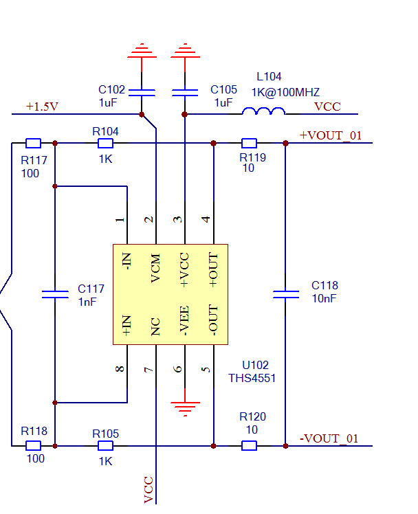
We try to use the ths4551 as a Diff buffer as the following schematic. There are four ths4551 in the design and the Vcom are connected together and set to a 1.5V ref. (The power supply VCC = 5.0 V )

The strange is that the quiescent current Iq of every ths4551 was as large 100mA, when ths4551s were soldered into the PCB.

With the same PCB, I tried the ths4521, which has similar pinout and function, the Iq is as small as 1.3mA just as datasheet saying.

Is there anything I missed? Any comments or help will be appreciated.

  • Hi Hai,

    I'm not familiar with this chip. But is C117 not a bit high? Wouldn't this introduce a huge phase lag in the feedback loop and cause instability by eroding the phase margin? I have had a look into the datasheet and found that when TI puts such a cap between the inputs, then they always combine this with a suited phase lead capacitance from the outputs to the inputs. So, I guess your circuit is oscillating.

    Another hint: If you use a LC-filter for the power supply decoupling, take care that you do not suffer from resonances! These ferrite beads usually offer a low frequency inductance of 1...2µH. This would give a resonance frequency of 130kHz in combination with C105, according to Mr. Thomson. At this frequency the ferrite bead doesn't provide any equivalent series resistance to dampen the resonance. As result your decoupling scheme can become very high impedant at 130kHz, showing no decoupling ability at all.

    To avoid this resonance insert a small resistance R in series to the ferrite bead, according to R >= SQRT(2xL/C). In your case R >= 1.8 Ohm would be appropriate.

    Best solution would be to decouple with a pi-filter. This would eliminate the influence of cabling. So, put in front of the ferrite bead and series resistor another 1µ decoupling cap, so that the decoupling scheme looks like a "pi".

    Kai
  • hi Kai, your replay is so informative and I learned a lot from your reply. I will try your suggestion.