This thread has been locked.

If you have a related question, please click the "Ask a related question" button in the top right corner. The newly created question will be automatically linked to this question.

THS4082: Behavior at input over voltage

Part Number: THS4082

Hello Forum,

my op amp is supplied with +-15 V as an non inverted amplifier. Input signals are sinusoidal signals at 500 kHz. My input resistor is 1k3 ohms. Gain is approx. 1.1.

What happens when the input voltage is above +- 15 V ? In my simulation the current  and power consumption increases. Can I destroy the THS4082 under these conditions?

Thanks for your answers!

  • Hi Daniel,

    yes this can damage the chip. Have you read the section "absolute maximum ratings" in the datasheet of THS4082?

    Kai
  • Hi Kai,

    yes of course, but this depends on the current which is limited by the resistor in my opinion?

    "Can" damage must depend on the current , or not ?

    Thanks for your reply.
    Daniel
  • Hi Daniel,

    It would depend on the input current rating if there was an internal clamp diode, but since there is not one specified in the datasheet, you cannot exceed the rail voltage on the input without using external clamp diodes between the input and the rails.

    Best regards,

    Sean
  • Hi Sean,

    thank you very much for your reply. I only could find the input resistance of the THS4082. Do you have maybe the power to figure out how much input current is accceptable?


    I have clamped the input voltage to the power supply with a diode, but this doesn't work because the opamp clamps the voltage earlier at slightly above Vcc. In addition I'am using an input resistor of 1k3.

    Thanks for helping me.

    Daniel

  • Hi Daniel,

    All I have is the datasheet. What is slightly above? Can you use external 0.2V Schottky diodes from Vee to V+ and from V+ to Vcc?

    Best regards,

    Sean
  • Hi Sean,

    in general the capacitance of Schottkly diodes is higher, I have to check if this is possible. With a schottky diode the 15 V will be exceeded as well?
      

    Thanks a lot.

    Daniel

  • The input voltage at the opamp with external diodes will be higher than the rail voltage and higher than allowed (15 V + UF), due to the forward voltage of the diodes. A current begins to flow, and I want to know the maximum current where the internal structure will be damaged. For example 15 V +- supply, input resistor 1k3 ohm, input voltage 20 Vpeak sinusoidal signal, rms current in simulation is approx. 1.85 mA. Can this lead to a destruction of the opamp?
    Thanks a lot.
    Daniel
  • Hi Daniel,

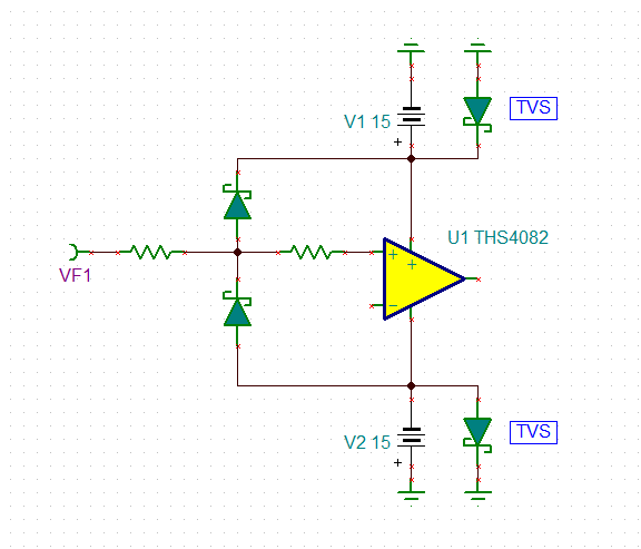
    I would use this scheme:

    The first resistor limits the current through the Schottky diodes. The Schottky diodes clamp the input voltage of THS4082 to the supply rails and limit the overvoltage to the turn-on voltage of these Schottky diodes. The second resistor, finally, limits the current into the +input of THS4082. The advantage of this two stage protection scheme is that the overvoltage seen by the second resistor is only the turn-on voltage of the Schottky diode! This allows the input current to be limited to very small values without the need of big resistance.

    From the supply pins to signal ground TVS are mounted. These shall limit the supply voltages to a safe value, if the supply lines cannot absorb the currents flowing through the Schottky diodes.

    But again, as the datasheet does not specify any allowed input current in the situation of input overvoltage, I don't want to give any guarantee that this scheme will work. You may use it at your own risk.

    Kai

  • Hi Kai,

    thank you for the comprehensive description. I will think about it. 

  • Hi Daniel,

    Please indicate whether or not this has resolved you issue.

    Sean