This thread has been locked.

If you have a related question, please click the "Ask a related question" button in the top right corner. The newly created question will be automatically linked to this question.

Circuit to convert a voltage output of a Hall device to a current.

Other Parts Discussed in Thread: OPA548

Hello,


I would appreciate some help designing a circuit to convert a voltage signal to a current signal.  Here is my attempt at a schematic for the circuit.


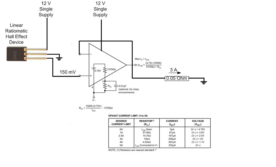
I don't see a need to use the current limit function included in the diagram.  If over current is a concern, I think I will use a fuse in the output.

Thanks to everyone who takes a look at this and helps me out.


Rick

  • Hi Rick,

    It will help us to understand a bit more about what you are trying to do, so I have some questions:

    The 150mV output from the Hall device... does it vary from 0V to 150mV?

    Do you want the output current to vary 0A to 3A, proportional to the output from the Hall device?

    Must the 0.05 ohm load be ground-referenced?  Could it be floating?

    Can you supply information on the Hall sensor?  Does it have a buffered low-Z output?

    The approach you have shown would dissipate (12V)(3A) = 36 watts. This is quite a lot of dissipation so the complete circuit will get HOT. There are two possible alternatives:  1) Run the op amp from a lower supply voltage, if available.  2) Use a class-D type amplifier.

    Regards,  Bruce.

  • Hi Bruce,

     The Hall Device voltage represents a current in a separate conductor of 5 Amps.  That 5 amp current produces a magnetic field in a gapped toroid core of about 30 G and the Hall device sensitivity is 5 mV/G.  The requirement is to measure the current over a narrow range (4 to 6 A) very accurately (<0.1%).  The Hall device is an Allegro A1321 and the output is push-pull.

     I don’t know if it is possible to avoid the ground reference for the output resistor.  The current measuring instrument is a Yokogawa WT 1600 power meter which has a current transformer input stage with 25 milli-Ohms of resistance. The 50 milli-Ohm includes some added resistance to achieve the correct output current.

     I think the output power will be 0.05*9 = 0.45 W but I don’t know what the input will be.  A heat sink will be required.

     At this point, I would like to stay away from PWM.

     Thanks so much for your interest and I look forward to your further comments.

     Rick

  • Rick,

    It sounds as if the 0.05 ohm load is a winding of a current transformer, correct? It would seem that this load could then be floating and would not need to be ground referenced. This could simply the circuit used to drive the 3A current.

    Your power calculation is the power dissipated by the 0.05 ohm load which is small by comparison. The power that must be dissipated by the amplifier drive circuitry is 36 watts at 12V operation. (Actually about 35.5 watts, accounting for the power delivered to the 0.05 ohm resistor.) This will require a large finned heat sink. I just want you to consider whether this is practical before we design a circuit.

    Another comment... the spec on the Allegro Hall device shows an operating voltage of 5V with an absolute max of 8V. It should not be powered from 12V as you show it. Furthermore it is shown to be on last-time-buy status on the Allegro site.

    Regards,  Bruce.

  • Hi Bruce,


    Yes, the input CT has a winding resistance of 25 milli-Ohms on all ranges.  If you can find a return for the current, the output can float.

     I didn’t show the voltage divider that I use to decrease Vcc for the A1321 to prevent clutter on the diagram.  I have A1324 units on order (delivery in 6 weeks) and a stock of A1321 devices on hand.  The Burr-Brown OPA548 operates on any (single) voltage from +8 to +60 V and the performance is not significantly affected over the full range of the supply voltage.  Power loss is not an issue.


    Rick

  • Rick,

    Here is a possible circuit for your consideration. I agree with your selection of the OPA548. The 150mV signal is amplified by a gain of 40 and impressed on R3, making 6V on R3. The 3A in this resistor flows through your load, RL.

    R3 is chosen to drop half the supply voltage on itself rather than the amplifier. This splits the 35.5 watts of dissipation between R3 and U1. Both will still get hot.

    The accuracy and temperature stability of R3 will directly affect accuracy. The current flowing in R1 + R2 creates a tiny error but it's proportional to the signal value and can be neglected. Grounding technique will be very important due to the low value of R3. Kelvin-type connections of R2 to the high side of R3 and R1 and the input signal to the low side of R3 are critical.

    Regards, Bruce.

  • Bruce,


    I appreciate you efforts on this.  I hope to breadboard it next week and will drop you a note on the results.


    Rick

  • Rick;

    I would not use a fuse instead of the amplifier's internal current-limit circuit. With semiconductors, it is always a race between the silicon and the fuse to see which one blows first. The silicon almost always wins.