This thread has been locked.

If you have a related question, please click the "Ask a related question" button in the top right corner. The newly created question will be automatically linked to this question.

INA122 Off by ~50 mV?

Other Parts Discussed in Thread: INA122, TINA-TI, TLC251, TLV2372, STRIKE

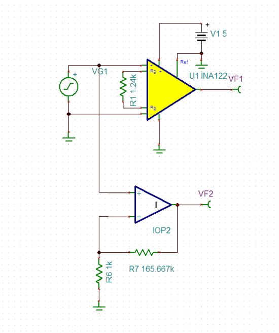
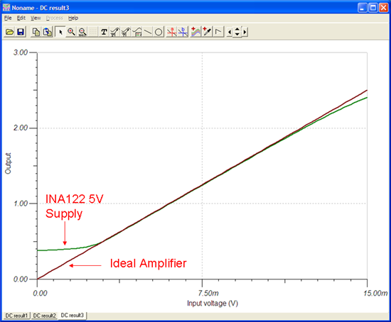
I am trying to amplify a 0 to ~15mV signal to a 0 to 2.5 V range using the INA122 op-amp. I calculated the gain using the equation supplied in the data sheet and adjusted a potentiometer to produce such a gain. However, the gain is well out the range of the specified error. The amplified signal is about 50 mV less than anticipated. The ref pin is currently grounded and the output of the INA122 leads to an ADC.  The signal is produced by a pyranometer, which produces a current that I've converted to a voltage with a resistor.  The negative output of the sensor is connected to Vin- on the INA122, and is also grounded.

Thank you in advance for any help and my apologies if the problem is trivial, I'm quite new at this.

  • Hi Nipun,

    Are you seeing a 50mV difference across the entire 0 to 15mV input range? You did not mention how you are supplying power to the INA122. In order to ensure proper operation of the part, you must provide power supply voltages that will limit the output swing during expected operation. For your application I would recommend powering the INA122 with at least +/- 3V, with +/-5V or more being better. You will notice if attempting to operate the part from a single supply, the output will not be able to reach 0V and this will cause inaccuracy in your readings.

    Also, a potentiometer introduces several possible sources of error in a precision circuit. The reason being that not only do potentiometer values drift significantly over time and temperature, but also pressure applied to the wiper during adjustment can cause errors in the resistance during adjustment. For your required gain of 166.67, I calculate that you would need an Rg of 1237.11 Ohms, the closest 1% resistor value is 1.24k Ohms, which would be a gain of 166.29 (neglecting errors due to tolerance).

    One final word, current to voltage conversion using a resistor may not be the most accurate method. Although an ideal current source would have an infinite output impedance, most real-world sensors do not (I was actually under the impression that pyranometers output a voltage, not a current, is yours a unique type?0. This finite output impedance will be in parallel with the resistance used to convert the current to a voltage and can cause an error in the output voltage. For example, below I show two 15uA current sources, one with a 100kOhm output impedance, and one with a 100GOhm (Giga Ohm) output impedance. Both use a 1kOhm resistor to perform current to voltage conversion, but notice the difference in output voltage:

    A solution to this issue is to use a transimpedance amplifier rather than a simple resistance for your current to voltage conversion. Below I show an ideal opamp, configured as a transimpedance amplifier with a gain of 1000V/A, notice that the output voltage is now the ideal/expected value (although inverted in polarity) even with the current source's finite output resistance.

    This is because the transimpedance amplifier looks like a VERY small impedance to the current source and so the error created by the source resistance in parallel is now much much smaller. Just something I felt you should consider!

    Good luck with your project!

  • Hi John,

    First of all, I'd like to thank you for your prompt response!  I am powering the INA122 with a +5V from a regulated microcontroller power output, which in turn is being powered by a single 6V lead acid battery.  Since the output is never able to reach ground does that mean there is an offset in the amplification? Or does that mean I just won't be able to accurately read very low values?

    I was not aware that potentiometers drifted so much and I will replace it soon.  In fact, that could be the main source of error because sometimes the error drops down to ~20 mV and sometimes it goes up to the ~50 mV I was seeing earlier.  

    Finally, the pyranometer I have does output a current, and it is bridged with a 147 Ohm resistor as recommended by the datasheet (http://www.licor.com/env/pdf/light/200.pdf).  I think I will try building the transimpedance amplifier circuit you mentioned as I am trying to make this as accurate as possible.

    Thank you again for all of your help!

  • Hi Nipun,

    That is an interesting device, it looks like it uses a silicon-based photovoltaic rather than a thermopile array for to measure total solar radiation. I recommend that you download Tina-TI (http://www.ti.com/tool/tina-ti) and simulate your circuit to see the effects of different gains and power supply voltages. To see how a 5V single supply effects the amplifier's performance, I simulated the INA122 (5V supply, 1.24kOhm gain resistor) and compared it to an ideal amplifier with exact resistor values:

    I performed a DC transfer characteristic simulation which plots the output of the INA122 for an input of 0 to 15mV. From the plot we can see that the INA122 deviates from the ideal for very low inputs as well as inputs on the upper end where it nears the limits of its output voltage range.

  • Hi John,

    I greatly appreciate your help and I will continue to work at it. I will post an update if necessary. 

  • Hi,

    I have the same pyranometer (LI200SZ) with a 147 ohm attached for measuring voltage.
    I'm trying to connect to an Arduino, with a TLC251.
    The max voltage of pyranometer is 10mV, so i need a gain of 500 to utilize the 0-5V range of Arduino.

    In datasheet of LI200 they mentions that: The shield of the coaxial
    cable is positive and the center conductor is negative. This is done because
    the trans-impedance amplifier used in LI-COR light meters requires a
    negative signal.

    This pyranometer has a silicon photovoltaic detector mounted (not a thermocouple type).

    My question is in relation to which the circuit for the amplifier should I use: Inverting, Non-Inverting or a Difference Amplifier.

    Is the TLC251 a good choice?

    http://www.ti.com/product/tlc251
    http://www.licor.com/env/pdf/light/200.pdf
    http://www.fondriest.com/pdf/li-cor_190_200_manual.pdf

    Thanks,

    Carlos Esteves

  • Hi Carlos,

    I'm not sure what the best choice amplifier is, though it looks like the TLC251 will work. In my application, I ended up using a TLV2372 [1] rail-to-rail single supply op-amp. The type of circuit you should build is called a Transimpedance Amplifier Circuit. More information can be found at [2] about halfway down the page. Note that the current should be flowing into ground. While I didn't do this, it might be a good idea to use multiple gain stages to help reduce noise. And finally, I believe that TI has transimpedance amplifier ICs; it might be worth looking into. Let me know if that helps!

    [1] http://www.ti.com/product/tlv2372

    [2] http://www.newport.com/Tutorial-Optical-Power-Measurement/139634/1033/content.aspx

  • I'm a little lost.

    Before publishing my first review and after doing some research on opamps, I found an article in Make magazine on sensors, and I was building my circuit through this scheme, in which the gain was given by 1 + (R2/R1). Then I discovered that my pyranometer was not the thermocouple type, but the solar type. So I went back again looking for schemes, and I found this site.

     In the Transimpedance Amplifier link figure, an Rf and Cf appears, which Cf do you advise?  And the Vout = -Vin * Rf right?

     I have another question regarding the pyranometer wires.

    The black wire that has a resistance is negative (center), and red is positive (shield).

    According to the image, I should connect the positive lead of the photodiode (the red pyranometer) to the negative input of the amplifier, is that correct?


    Will the Vout come negative? If I need it to come positive, what should I do?


    Regarding the gain and resistance to use, I would appreciate if you could confirm the following calculations:

     If: Vout = Vin*Rf,  Vout (max) = 5V,  Vin(max) = 10mV

     5V = 10mV(E-3)*Rf  ⇔   Rf = 500 Ohm

     i.e., I need a 500ohm resistor in order to move from 0-10mV to 0V-5V, correct? For this circuit, the resistance value is the gain value, isn’t it?


    Having a resistance in one of the pyranometer wires allows to measure voltage instead of current, but don’t the transimpedance amplifier converts current to voltage? Isn’t the signal coming out of the pyranometer voltage? I'm confused.

    Thanks,

    Carlos Esteves

  • Hi Carlos,

    I'm a little confused on your classification of positive and negative wires. Just to clarify, from page 2-2 from the LI200 Manual [1]: "The shield of the coaxial cable is positive and the center conductor is negative." I will be using this classification from here on.

    Second, you said you have a Li200SZ sensor which, according to [1], should terminate in bare leads and not have any resistors attached to it. If you have attached the 147Ohm resistor to it, you will need to take it off for the transimpedance amplifier circuit. (BTW, you are correct. The purpose of the transimpedance amplifier is to convert a current into an amplified voltage. Since the Li200 is a current source, you no longer need the 147Ohm resistor)

    Onto the amplifier. If you connect the positive lead of the Li200 (the shield) to the negative terminal of the op-amp, you will get a negative voltage output from the amplifier. From what it sounds like, you want a positive output from the amplifier so you can interface with an Arduino. To do this, you will need to connect the positive lead of the Li200 (the shield) to ground, and the negative lead of the Li200 (the center conductor) to the negative terminal of the op-amp. Note that the positive terminal of the op-amp is also connected to ground.

    Now, the calculations. If the current is flowing into ground like I described in the previous paragraph, Vout = Is*Rf, where Vout is the output voltage, Is is the current produced by the sensor, and Rf is the resistor shown in the diagram in your post. The Rf that you should choose is based on your individual sensor, and what kind of environment you want to use this in. For example, let us assume you have a Li200 calibration constant of (90.00 microamps / 1000 W/m^2). Let's also assume that you would like to use this anywhere in the world, and will therefore see a maximum (assumed) sunlight of 1200 W/m^2. To calculate the current from the sensor at that radiation...
    (1200 W/m^2) * (90.00 microamps / 1000 W/m^2) = 108 microamps = 108E-6 Amps
    Now, to give yourself a little headroom, we'll assume that you want a 4.8Volt output with radiation of 1200 W/m^2. Using Vout = Is*Rf...
    Vout = Is*Rf  --> Vout / Is = Rf  --> (4.8V)/(108E-6A) = 44444.44Ohms
    Therefore, you'll want a 44.44 KOhm resistor to achieve a gain of above. I have been told that it would be good to break the gain into two stages though so you might want to experiment with that.

    Onto the capacitor. The capacitor is there to reduce oscillations and noise. You will choose the capacitor based on the frequency you want cut off. Let's assume you use a 1 microfarad capacitor...
    f = 1/(2*pi*Rf*Cf) = 1/(2*pi*44444.44Ohm*1E-6F) =  3.581 Hz [2]
    Therefore, if you want to filter out any signal faster 3.581Hz with the above configuration, you should use a 1uF capacitor.

    I think that answers all your questions, let me know if you are still confused. 

    [1] ftp://ftp.licor.com/perm/env/Radiation_Sensors/Manual/TerrestrialSensors_Manual.pdf
    [2] http://www.wolframalpha.com/input/?i=1%2F%282%2Api%2A44444Ohm%2A1e-6Farad%29 

  • Hi Nipun,

     I have no words to thank you for your help.

     I've been doing the calculations with the constant value indicated in pyranometer:

     Multiplier: -10,56 (W/m^2)/microamp

    Multiplier = -1 / Cal.Const

     Cal.Const=-1 / -10,56 = 0,095 micramp/(W/m2)

    Through information obtained on NASA website, the value for solar radiation is 1368 W/m^2.

    1368*0,095 = 129,96 microamps = 129,96 E-6 amps

    Vout = Is * Rf ⇔ Rf = 5V / 129,96E-6 amps = 38473,38Ohms = 38,47KOhms


    Despite having made these new calculations, I ended up connecting the pyranometer with values indicated by you. (Rf=44,44KOhms).

    I made the connections as you indicated me and I seemed to be getting good results, despite the constant oscillation between values​​. I did not use a capacitor, these oscillations may be due to this? 

    I connected the VDD-/GND to the GND and the oscillations decresead, was it right to make this connection?


    Another question that I still have is regarding to the capacitor, how do I know how much frequency should i cut off?

    The figure below is a scheme that was on the TLC251 datasheet, where a capacitor of 100 pF appears. Should I use this or is this merely illustrative?

    Click here to play this video

    Again thank you so much for your previous answer, it really helped me.

    Best regards,

    Carlos Esteves 

  • Hi Carlos,

    I'm glad to hear that I could help you! First, I do not think you need the 100pF capacitor that is shown in the data sheet. To be honest, I'm not completely sure what it does but my transimpedance circuit seems to work fine without it.

    However, you do need the capacitor that is shown in the transimpedance circuit (Cf on the above diagram). This capacitor prevents oscillations in the circuit. The value of the capacitor is a design problem: exactly how much noise do you want filtered out? Planet Analog has an article where they show you how to calculate the minimum capacitance you will need to eliminate oscillations [1]. However, I think it is a good idea to filter some noise out, so I used a larger capacitance. In the end, the capacitor value you should use will need to be greater than a certain value, as calculated by [1]. After that, you should choose a value that filters out frequencies that you are happy with (and you can calculate that by using the equation from my previous post). Also, you should also have VDD-/GND hooked up to ground. I'm surprised that circuit worked without that.

    Finally, I haven't read the datasheet for the TLC251 completely, but I'm not sure what Offset N1, Offset N2, and Bias Select do. You should make sure you understand those functions before using the IC in your application.

    Let me know if that helps!

    [1] http://www.planetanalog.com/document.asp?doc_id=527534&site=planetanalog

  • I too have a Li Cor Li-200SZ pyranometer and I would like to build a DC amp for it to give 0 to 10 vdc using single voltage opamps. .

    I am having trouble interfacing the negative center conductor to an op amp.  Connecting the shield to the op amp works OK, but I would rather connect the negative input to the op amp. 

    Has any of you folks successfully got this to work?

    Thank you


  • Hi Frank,

    Ultimately, I ended up not using the INA122, but instead I built a transimpedance amplifier for the Li-200. Since you have such a large gain, you may want to use multiple stages to get to the full range you need. Finally, I believe TI sells transimpedance amplifiers in IC form if you didn't want to build one yourself.

    - NG 

  • Thank you for taking the time to respond NG and thank you for the links.


    If you don't mind, I would like to ask a couple of questions.


    How did you connect the center negative conductor to the op amp.  And which op amp did you use?

    Also, how complicated was the transimpedance amplifier you built?  I read the wikipedia link your provided and that circuit looks pretty simple.  I'm not sure whether that circuit is set up for a negative input as offered by the pyranometers we have.

    Thank you NG,

    Frank

  • Hi Frank,

    Can you explain more what you mean about connecting the negative conductor? Do you mean which terminal I hooked it up to?

    The op amp I used was a TLV2372 from TI. A picture of the circuit I used can be found here: http://imgur.com/KDVTEZi. The positive terminal of Li-200 is connected to the positive terminal of the op-amp. You will of course have to change the resistor and capacitor values to account for the gain and filtering you need. An electrical engineer I was talking to suggested that I use multiple op-amp stages to reduce noise, but I did not do that for my application.

    Building the circuit was not very difficult. That said, I am not an expert at analog electronics so there might be something that I missed.

    Hope that helps.

    - NG
  • Thanks for the circuit NG. And thank you so much for the guidance. This is really helping!

    What I meant: I was wondering whether you ended up running the positive lead (the shield) of the Li-200 to the opamp. And did you ground the negative center conductor.

    I just 'built' the circuit in LT spice. I used your values (and I didn't use the '147 ohm resistor bridging resistor'). With 90 uA from a current source, I get around +14 mV to the opamp. I get 4.0 volts out of the op amp. I think that means I would have positive shield connector to the opamp negative input.

    With no current from the opamp, I get zero volts out of the op amp.

    Does any of that make sense and sound OK?

    Thank you for the help NG.

    Frank
  • Hi Frank,

    The 4.0 volts sounds about right. I designed the circuit to be used with a 4.5V reference, and using 90uA/1000 W/m^2, should give 4V.

    I don't have a Li-200 in front of me right now, but I designed it so the lead where the current comes out of (which I call the positive lead) should be connected to the positive terminal of the op-amp, which is also connected to ground. The other lead should be connected to the negative terminal of the op-amp. I double checked my math on the schematic I uploaded and I think it makes sense.

    You are also correct in that you don't need the 147 ohm bridging resistor. I believe that's only necessary if you use one of Licor's data loggers.

    - NG 

  • Hi NG.

    I want you to know I appreciate every piece of information you provide.  The Li-200's provide a negative voltage on the center conductor.  And positive on the shield.  I am glad you developed an operable way to interface it to the op amp. 

    My Li-200 will end up being about 50 feet from my processor.  The Li-200 has to mount on the south edge of the roof and that edge is not at all convenient to get to.  Because of that, I am trying to make my best guess as to how to run the cables for it.  So the big question of the day is:  From your experience, could I run a piece of coaxial cable for the entire distance?  Another option is to run about 18 feet of coax from the Li-200 down into my garage where I could put the circuit board.  And then run about 30' of cable from there to the processor.

    I've ordered a TLV2372 to provide two stages of gain.  I am wondering whether I can just run the output of the second stage to the processor or whether I should place a 2n2222 buffer on the board as the output stage.   The TLV2372 data sheet states that it can be powered by up to 16 VDC, so it seems an output of 0 to 10 volts is reasonable with power from a 12 volt regulated supply.

    I'll appreciate any advice you can provide NG.


    Thank you!

    Frank

  • Hi Frank,

    To be honest I don't have a lot of experience with what you're asking so I don't know how much I can help you. My intuition is that you don't need to use the 2n2222 buffer and the output from the TLV2372 should be fine connecting directly to your processor.

    As for the cable length, I have no experience experimenting with something like this since my Li-200s were very close to my processor so I just used the default cable length. My two biggest concerns are noise and resistance of the cable. My hunch is to use the 18' of coax to the circuit board (which I assume has the TLV2372), and then run another cable to the processor. I would also recommend using a filter close to your processor to filter out any noise that you might pick up. Finally, this may be obvious but since this is going around and through a (residential?) house, you should do your best to avoid phone or power lines. I would assume they would add quite a bit of noise to the signal which is undesirable. At least with the power lines the noise will be around 60 hz (if you're in the US) which should be simple enough to filter.

    I think to find out for sure you may just have to play around with it.

    Sorry I couldn't help more with that aspect.

    - NG
  • Thank you NG.

    Yes, the TLV2372 will be on the "circuit board".  The sensor will be on the roof of my residence here in the US.  I appreciate the advice regarding noise filtering.  That is what I am concerned with most.  The Li-200 can be purchased with 50 feet of coaxial cable attached.  So, for that reason, it seems that the sensor could be 50 feet from the processor.  Maybe that is somehow in some sort of ideal environment away from noise sources such as the 60 Hz electrical interference and telephone lines you mention. 

    I will try to figure out a way to attach 50 feet of coaxial cable to the sensor and string it around the house without running it through walls, etc. just for a test.


    Again NG, thank you for the help!


    Frank

  • If Licor sells them with 50 feet of coax attached, then I agree, it seems as if that should be fine as far as implementation goes.

    One last note: I did a bit of googling and found this article which talks about wiring instrumentation and avoiding noise when near power lines. I think the main points are to cross cables at right angles, and to use steel conduits when possible.

    Good luck with your project!

    - NG 

  • I did build the amplifier and used 50' of coax cable. It worked perfectly for three weeks until a storm hit a few days ago. The pyranometer is still OK. But the TLV2372 is dead. I am thinking of putting diodes in both directions from the negative input of the opamp to ground. Not sure which diodes to use if that matters.

    Do you have a suggestion for how to protect the opamp input? I assume that is how the damage occurred. The regulator for the opamp is still OK.
  • Hi Frank,

    Unfortunately, I don't know how to protect the opamp input - I have never run into that problem before. If the op-amp failed because of too much voltage, then I think the diodes will work but I'm not certain. Regardless, I would test the circuit to see if the diodes affect the signal at all. The other, less elegant solution is to place the TLV2372 into a DIP socket, which then goes on the PCB. That way, if it does get damaged again, it is trivial to replace it.

    - NG 

  • Send a complete schematic showing power supplies. Also send link or sensor datasheet and cable length and type of cable.
  • Hi NG. Thank you for the reply. I did put the IC in a socket to begin with. I was waiting for the stormy weather to die down a little first. I only had two of the IC's.

    I figured I would replace the IC and then at a time with maximum sunshine, I will bridge diodes across the input to ensure there is no change in the output level.

    Thanks again!

    Frank
  • Hi Tim, I am going to assume you are asking me to provide this info since I am the one with the dead TLV2372. I truly appreciate your offer. I will pull the information together and attach it.

    Thank you,

    Frank
  • Hello Tim.  I am going to try to attach the schematic a couple different ways.

    I inserted a pdf of the schematic.

    and
    Here is a link to a jpg:

    Pyran Amp.pdf

  • It seems the link to the PDF and the link to the jpg worked OK. Please let me know if you have any questions.

    Frank
  • Thank you Tim.  So you are saying to insert one 10k resistor in series with the input and scrap the diode idea.

    Also I think you are showing that the opamp already has a couple of diodes on the input internally.

    I tend to believe there wasn't any direct lightning strike.  The pyranmeter is mounted on the roof but at the eve of the roof.  So there are other higher objects around it.  And we were home during the storm and while there was rain and lightning, there was no lighting in proximity to our house.

    Another issue I was wondering about was when there is a bright flash of lightning that the pyranometer 'sees' would that cause a voltage (current?) spike to be sent down to the opamp.  I don't know whether the pyranometer could repsond that quickly.  But if it does, could a capacitor be placed from the input to ground?  Maybe on the opamp side of the 10k resistor.  And maybe the brightness of lightning is much less than overhead sun anyway.  But other than that, I fail to understand what could have harmed the TLV2372.

    Thanks again Tim for your expertise with this.  I and others will benefit!

    Frank 

  • With the recommended protection resistor it will also help if there was any static electricity (ESD event) into your assembled circuitry. Do not add a resistor to the op amp side of the 10kohm resistor as it will cause stability problems. I have not researched enough in detail the pyranometer characteristics but doubt if it can put out enough current to become a problem.
  • Thank you Tim. I'll proceed with the series 10k resistor. You said not to add a resistor to the op amp side of the 10k. I believe you meant to type, "do not add a capacitor...". I won't.

    The current output of the pyranometer is very small.

    Thanks again Tim,

    Frank
  • I am pleased to report, I replaced the TLV2372 and added the 10k resistor and pyranometer readings came back to life. I haven't checked calibration yet. I will update the schematic and upload it here in case someone else would like to use it. We are expecting storms tonight, so fingers are crossed.