This thread has been locked.

If you have a related question, please click the "Ask a related question" button in the top right corner. The newly created question will be automatically linked to this question.

Phone current measurement using high-side shunt monitor

Other Parts Discussed in Thread: INA193, INA194, INA216, INA118, TINA-TI, INA210, PGA280, INA333

Hi,

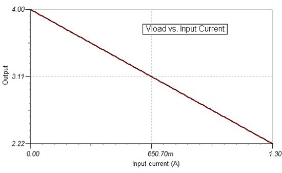
I have been measuring the energy consumption of some smartphones using a shunt resistor, but now I would like to add a shunt monitor (unidirectional is enough). Basically, I remove the battery of the smartphone and connect it to a 4V power supply with a shunt resistor between the power supply and the V+ pin. 

The current range is 1.4mA to 1.3A: (measured with a DMM (U1252B))

- 1.4mA (Screen off, Flight Mode)

- 20mA (Screen off, Bluetooth idle)

- 160mA (Screen on, flight mode)

- 700mA (CPU 100%)

- 1.3 A (Everything switched on)

The input of my DAQ is +/-10V. I decided to use an INA216A1 (Gain=20) with a 0.2 Ohm shunt resistor. However, the package is too small for my purposes.

I have tried with an INA194 with an additional power supply of 5V only for the INA but the gain was too high. I wanted to try with INA193, but I decided to ask first. I am concerned because it seems that I have to sacrifice the accuracy of the measurements for low currents in order to have a high dynamic range. For the best accuracy I am required to create a Vdrop from 50mV to 100mV, which becomes difficult.

Is there any shunt monitor like the INA216 but with a bigger package (like SOT23-5)? Or should I use an instrumentation amplifier instead?

Thanks very much in advance,

Ekhiotz

  • Hello Ekhiotz,

    I am working on this and will get back with you tomorrow.

  • Hello Ekhiotz,

    With a 200mohm shunt and 1.4mA load current, your sense voltage is just 280uV.  The INA193-8 devices have 2mV input offset, which is much larger than your sense voltage.  

    The difficulty with this application is that the load current range is very large (1.4mA to 1.3A).  If we map this current range to your DAQ input of +/-10V (let's just use 0-10V for ease of design), the gain should be less than 7.7V/V ((10-0)/(1.3-1.4m)).  None of our dedicated current shunt monitors have such a low gain.

    I assume that you have +/-10V or similar dual supply available.  Since your Vcm=4V, I would recommend using an instrumentation amplifier.  I have attached a TINA SPICE simulation using the INA118, which comes in an SO-8 package.  Here is a brief description of the circuit:

    a)  +/-10V supply
    b)  Gain=5V/V
    c)  Outputs ~10mV to ~9V for the corresponding currents

    d)  Rsense=1.37ohms
    e)  Light load accuracy of 7.7% (worst-case)

    From here you can modify the simulation by downloading TINA-TI from http://www.ti.com/tool/tina-ti

    I hope this helps.

    Ekhiotz.TSC
  • Hi Pete,

    Thanks very much for your answer. I downloaded the program and file and I was trying to go through your design. 

    I had a look to the datasheet as well, and I see that I could only use a dual power supply.  I have a +/-15V power supply in my DAQ, I hope it works. 

    I have a question about the worst-case error of 7.7%. I see that it is computed with the minimum current. Which means that this error decreases when I increase the input current, meaning that it has better accuracy in the middle of my range than in the lower part.  In principle I could calculate the error for all my possible input current values, right?

    You chose an Rsense which is bigger than the ones I thought. Given that the phone impedance varies from 37kOhm to 10MOhm, do you think that by calibrating the measurements with known resistors I could get rid of the small increase in impedance due to Rsense?

    Thanks very much again!

  • Hello Ekhiotz,

    You are correct.  The worst-case error will occur when the load current is smallest.  We wrote an article series at http://www.eetimes.com/design/industrial-control/  Accuracy is discussed in Part 3, which was published yesterday.  How timely.

    The tradeoff with respect to the sense resistor is the voltage drop at maximum load current versus accuracy at minimum load current.  With a 1.3A load current, a 1.37ohm sense resistor will drop voltage such that ~2.2V will be available to your load.  Here is a graph of the voltage supplied to the load vs. the load current for the 1.37ohm sense resistor:


    If we decrease the sense resistor value we will provide more voltage to the load at the cost of accuracy at minimum load.  Changing Rsense to 1ohm will allow for 2.7V to the load.

    So, the question becomes:  what is the minimum voltage that your system can tolerate?  This will help determine the maximum sense voltage.

    In this type of application (cell phone test bench), however, we have seen cases where you may have control over the common-mode voltage.  In other words, you may be able to increase the 4V supply to essentially offset some of the sense resistor voltage drop.  Additionally you may also have room to increase the gain of the INA, thereby allowing you to use a smaller sense resistor. 

    I hope this helps!

  • Hi!

    Thanks for your quick answer and the link to the article accuracy, really well written and clear. There is a last thing that I did not fully understand. When the input current is 1.3A, the resistor will leave around 2.2V for the phone as you said. Does this mean that the phone will switch-off due to lack of voltage supply? It needs around 3.7V. 

    I think that the minimum voltage that my system can tolerate is around 3.7V, which means that with 4V I should use a small resistor that creates a Vsense of 0.3V max. Is that right?

    However, decreasing the shunt resistor will make decrease the voltage drop and therefore increase the error due to Vos. In your first schematic, the error decreases a lot when increasing the current (e.g., 37mA input, 0.29% error).

    Most of my measurements will be performed in the middle part (0.16A at least). Which resistor would you choose?

    I am thinking that I could also have different settings for different measurements by just changing the Rsense and Rg as you suggested. I would have to calibrate the output for both settings, but it would gain in accuracy in the lower part. What do you think? 

    Thanks very much in advance.

  • Hello Ehkiotz,

    No problem...I'm glad you enjoyed the article!  Your understanding of the sense voltage/system voltage vs. sense resistance vs. error is correct.

    I don't know exactly what will happen to your system if it requires 3.7V and is only supplied with 2.2V.  The best solution here is to ensure that your shunt voltage is <300mV as you correctly pointed out.  Similar to a minimum system voltage, is there a maximum system voltage?  For example, if the system can tolerate a supply voltage of 3.7V-4.3V, you really have 600mV to work with if you can easily increase the system supply voltage.

    I would size the shunt resistor for the 160mA setting such that the 160mA is in the center of the expected range.  I do not know what that range is, but you now have a solid understanding of how to translate this range to a shunt resistor based on all of the variables.

    Since your shunt voltage must be <300mV (assuming you can't increase the system voltage), you will be required to keep your sense resistor below 230mohms at maximum load.  At minimum load (1.4mA) this would correspond to a shunt voltage of ~300uV.  If you wish for 10% error, you will need an amplifier with 30uV of input-referred offset voltage.  We do not have any instrumentation amplifiers with such low input-referred offset voltage (the INA333 is the closest, but you may have supply/output voltage issues), so you will have to perhaps tolerate more error or see about raising the system voltage to offset some of the voltage drop (if feasible).  Or, you may consider using multiple devices (e.g. an INA210/1/2 for the minimum current measurement and a different device  for the rest of the measurements).  Also, there are some devices whose gain can be changed digitally (e.g. PGA280).  I have not thought much about this solution, but it may be the way to go here.  Finally, as you already mentioned, perhaps you could calibrate out the initial input offset voltage(s).

    A note about PCB layout:  I don't recommend switching sense resistors for the layout and switch selection (because the Rds(on) of the switch will be in series with the sense resistor) complicate matters and can introduce significant errors.  FYI, Part 4 of the article series discusses errors due to PCB layout.  It will be published in about 2 weeks.


    I hope this discussion has helped!

  • Great help! Thanks again!

    I do not need high-frequency measurements (almost all the signal is in low frequencies), so I could even manage without doing a PCB. Of course, the accuracy could be compromised...

    I will follow the Part 4, really interesting tutorial!

    I will post my final design when it is ready :)

  • Hi!

    Finally I finished the following circuit that would allow the phone to have 3.7 V (Vloadmin) based on your previous design:

    I also calculated the error due to the offset voltage and the CMRR:

    And I will calibrate the error based on measurements using different Rload resistors. 


    Again, thanks for your help!