This thread has been locked.

If you have a related question, please click the "Ask a related question" button in the top right corner. The newly created question will be automatically linked to this question.

How to implement and measure 4-20mA XTR115

Other Parts Discussed in Thread: XTR115, OPA320, RCV420

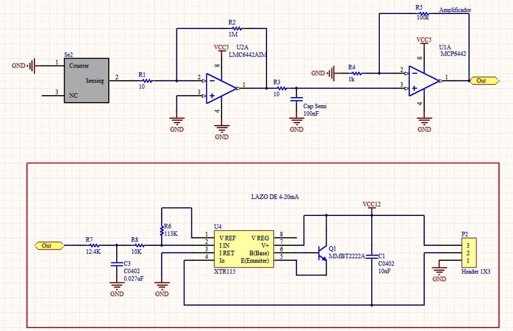
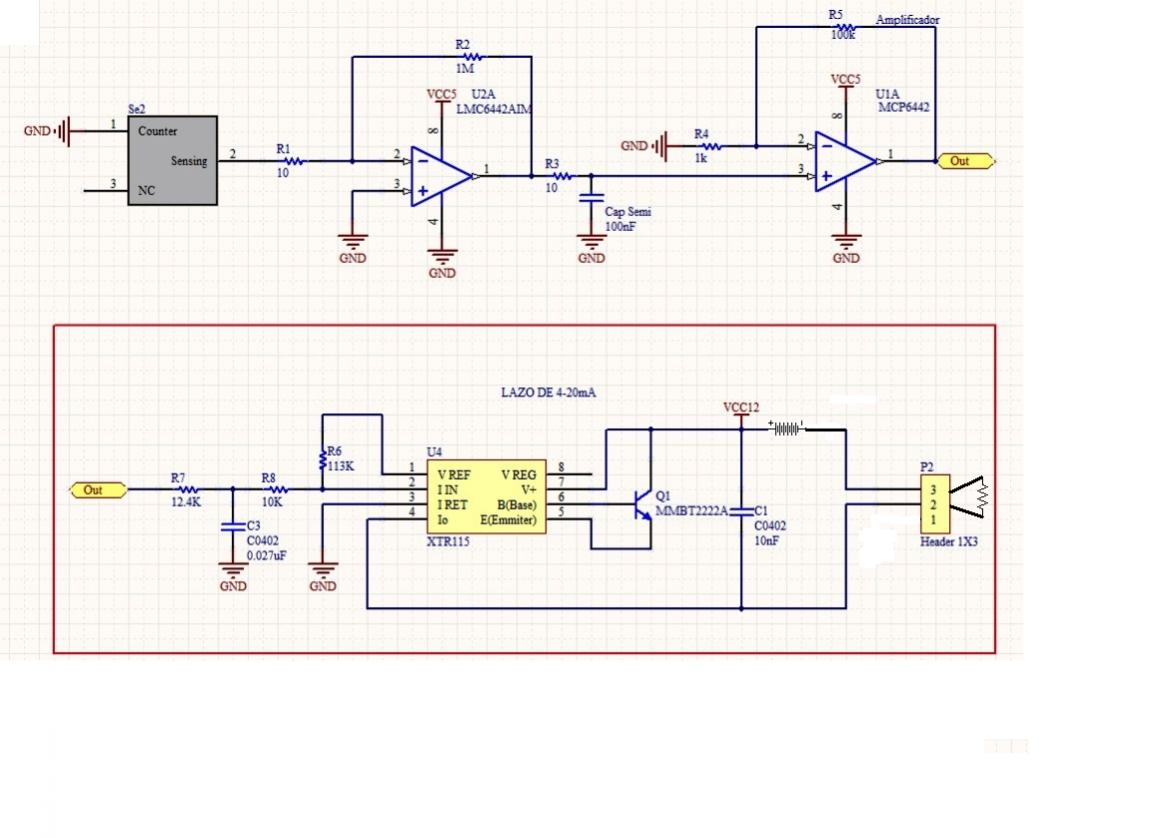
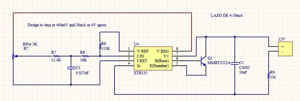
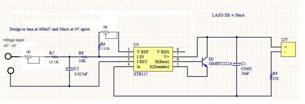
im trying to use this XTR115  but i dont know how to implement it or i have an idea but i doesnt work for me. I have a voltage range between 400mV to 3V from a Non Inverter Amplfication layer. I attached the way that im using it... but i always get an output current of 0mA.

So, i dont know if my trouble is of design, or maybe i dont know how to measure the current (i put the Tester's points parallel to te Capacitor of 10nF). 

  • Hi Ricardo,

    I'm unsure which capacitor you are referring to. Vloop in the diagram you attached is a voltage source for the loop (known as the loop supply). The XTR115 uses a transistor to control the current being drawn from that voltage source (4-20mA) which is most commonly measured across a resistor at the other end of the loop (RL in your diagram). It is also important to note that the proper method to measure current is with the meter in series with the loop, NOT in parallel to any component. 

  • Hello

    Thank you for your answer... and sorry because i didnt attach my own circuit... You will notice that i hace a 3 points connector and my point test ar between 1 and 2 ones... It shouldnt be there? that Vloop is another source supply?

  • Thank you for attaching your circuit. Yes, Vloop is the power supply shown by VCC12 in your schematic. As I mentioned in my previous post, you cannot measure current by placing the meter in parallel to C1, it would be better to place the meter in series with the supply VCC12. 

    Furthermore, 4 to 20 mA current loops are meant to be floating (not ground referenced) and because of this you cannot tie the I return pin (pin 3) to an external ground. All of the input circuitry return current must return through this pin as shown in the datasheet, on page 5:

  • Hello Jhon, geetings for you!

    Thanks for your atention and explanation... Really Comprehensible... But now i have another doubts:

    1. As you show me in the image, IRet is not grounded but how i could do that accord to my circuit design?... Now i attached a picture of the design where i took the my one, there the IRet is just to AGround so beacuse of that i did it... But again as i told you, i dont know how to do exactly what to do what you told me ...

    2. Between wich pins i measure the VReg and VRef voltages? Because i measure with the VLOOP and te resistor configuration shown in my "re-design circuit" (see the picture attached) and always are 12V...

    Thanks again Jhon!

    Regards

    Guide Design

  • Ricardo,

    I have re-drawn your circuit showing the proper configuration:

    I should point out that with such large amounts of gain in the amplifiers it is unlikely that you will get any usable output because of noise and offset issues. I would suggest verifying if your sensor actually requires such large amounts of gain. I'm a bit confused by your second question, it was my understanding that you were trying to measure the current in the loop, in which cause you need to either configure your meter to measure current and insert it in series in the loop (represented by AM1 in the attached schematic) or configure your meter for voltage and measure the voltage drop across the load resistor (R6 in the diagram) and divide this value by its resistance to determine the loop current.

  • Thanks Jhon!!!

    Is amazing your help..!! Finally i got an answer from the circuit, 28mA at the current loop with no variation... So i decided to take out the sensor circuit and the corresponding amplfication layer and put a potentiometer as you can see in the picture wich i attached. I did this because if i dont conect anything at the input of 12.4K resistor, also the current continue being 28mA. I variate the potentiometer and it doesnt happen anything. I measure the voltage at Ref is 2.5V and VReg 4.1V, this is refered to Iret pin.

    Now. according to your opinion about the huge Gain of my camplification circuits, is because the sensor is an electrochemical one wich drive nA currents, and at the CURRENT-VOLTAGE converter configuration i got mV measures, so i have to amplificate it. As everything you told me, is True that noise and interferance is high on it, but i havent found another way to do it, if you have more advices for me about this topic... Welcome!!

    Thanks again Jhon, and ill be pending fo your answers.

    Regards, Ricardo

  • Ricardo,

    I ran a quick simulation of the circuit you show (with the potentiometer) and this should produce different levels of output current in the loop. My simulation showed that varying the potentiometer should change the output current from 2.21mA to 24.53mA. I would verify that the circuit is constructed correctly and it may be a good idea to replace the XTR115 with a new part to eliminate the possibility of a damaged IC affecting the circuit behavior. 

    As for the amplifiers on the output of your electrochemical sensor, I would increase the gain of the current-to-voltage circuit and eliminate the second amplifier. I would also select low-noise and low offset FET input amplifiers. An example schematic with the OPA320 is shown below:

    Notice that there is a capacitor in parallel with the feedback resistor in the transimpedance amplifier. Along with ensuring the stability of the amplifier, this capacitor reduces the bandwidth of the amplifier, the thermal noise contribution from the feedback resistor, and therefore will reduce the output noise of the system. 

  • John, at first, i would like to thank you for your Amazing Help!!

    You have all the reason one more time cause that was my big problem, the XTR wich i was using was damage. I changed it and i have been doing some testing with the circuit i attached. The reason of the Potentiometers is to adjust the ZERO (Input 400mV - Out 4mA) and the SPAN(Input 4V  Out 20mA ) but i dont find the  exactly point to take this values.

    Your recommedation about the sensor's circuit is excellent, i will taken it into account, in this form and as you specified ill improve the price and low noise of my circuit.

    John , wich program do you use to simulate with the XTR? I download the TINA but i couldnt find it.

    Regards, Ricardo

  • Ricardo,

    I have been using a simulation model that was developed by a colleague, Collin Wells to approximate the basic behavior of the XTR115. I've attached the simulation file for you to use in Tina. The transfer function of the XTR115 is I_out = 100 * I_in, and the applications section of the datasheet (starting on page 6) has very good information on choosing the input resistor values. For a 4 to 20mA loop system, 4mA is the minimum current allowable on the loop, any current value less than 4mA indicates a fault condition. Therefore the offset resistor (R6) in your design needs to be chosen to produce a 40uA current into the input of the part when the output of the amplifier is 0V. 

    XTR115.TSC
  • Excellent John!

    All muy doubts and difficulties about this topic are resolve! I decided to choose the potentiometers wich i specified in order to adjust my Zero and Span as you told me to read the applications section of the Datasheet, and according to the Sensor's behavior (is really unstable).

    Excellent IC!!!

    Thanks again John, for your huge help and attention.

    Regards, Ricardo

  • Hi JJohn please send me an circuit in order to take the line XTR11.. for transmiter signal from 0 to 5V thanks
  • Hello Eduardo,

    Take a look at the RCV420 or a circuit using a dc accuracy single-supply op amp such as the one shown in this post: