This thread has been locked.

If you have a related question, please click the "Ask a related question" button in the top right corner. The newly created question will be automatically linked to this question.

Electrical conductivity measurement

Other Parts Discussed in Thread: OPA381, LMV793

Hi,

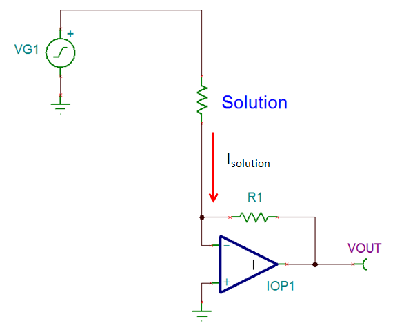
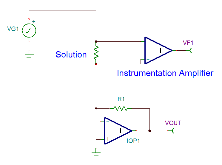
I want to measure the electrical conductivity in solutions, using a EC sensor that consists of one pair of electrodes immersed in a solution. When a voltage is applied between this two electrodes, the ions of that solution are attracted to the oppositely charged electrode and move toward it as the current flow in the solution. And so it is possible to measure the EC.

 To avoid polarization, an AC voltage must be applied. And this can be done by applying a filtered square wave from a microcontroller output. (square wave + filter = sine wave, if the filter is correctly applied)

We could see this EC like a variable resistor.

 I would like to know, what is the best way to measure the resistance value when an AC voltage is applied? I found a very poor website talking about using Wheatstone bridge, and using a differential amplifier.

Any others ideas are welcome,

Thanks in advance,

A. Paiva

  • Almerindo, 

    One method to perform this measurement would be to use a transimpedance amplifier. The type of amplifier converts an input current to an output voltage which can then be measured directly. Therefore, if you know the applied voltage, and the current that passed though the solution, you know the impedance of the solution Z = V/I or alternatively the conductance G = I/V. The basic setup would look like this:

    The output voltage of the op amp would be VOUT = - R1 * Isolution. Because the op amp holds its inverting terminal at the same potential as its non-inverting terminal, conductance of the solution G = Isolution / VG1. Remember this is conductance, not conductivity, the two are related in that conductivity = (conductance * length)/ (area). If the solution is of extremely high conductivity, then the resistances of the wires and electrodes in the system need to be accounted for in the measurement. This is normally done using a kelvin measurement setup:

    In this measurement system the voltage applied to the solution is now measured by an instrumentation amplifier in order to remove the voltage drop across the connections from affecting the measurement result.

  • Almerindo,

    John has provided some good basic circuits.

    You may want to consider whether it is really necessary to excite the liquid with a sine wave. A square wave may be okay and easier to process the output signal. If a low frequency is used--maybe 10Hz or so--a slope on the top of the square wave current output might give you an indication of polarization rate. Frequency could be adjusted if too much polarization is occurring.

    There is quite a lot of adaptation required in this circuitry, depending on the general range of conductivity measured.

    Regards, Bruce.

  • Hi Mr. John,

    Thank you very much for your answer.

    In your setup, could I use a single supply amplifier? I forgot to tell you that, I was considering to decouple the sine wave (or square wave as suggested by Mr Bruce) with a capacitor, so that the solution will be excited with +-2.5V.

    Could I use LMV793 or opa381? Would your recommend another part?

    The conductivity range is 0.01-2mS/cm.

    Best regards,

    A. Paiva