This thread has been locked.

If you have a related question, please click the "Ask a related question" button in the top right corner. The newly created question will be automatically linked to this question.

Basic RCV420 and XTR110 connections

Other Parts Discussed in Thread: RCV420, XTR110, XTR105, XTR111

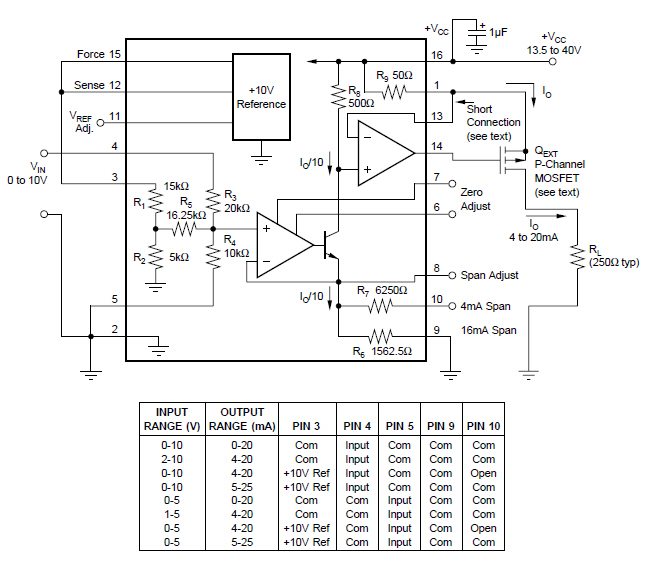
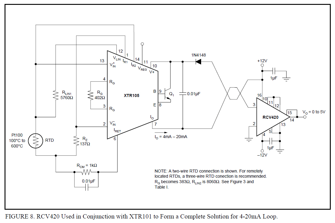
Ok, I am trying to connect a XL-MaxSonar-WR1-MB7052 sensor from MaxBotixInc (which output is voltage from 0 to 5V) to the XTR110 and then the XTR110 to the rcv420 and read this voltage with ADC module of PIC 16F877A from microchip; could you tell me how should I connect the xtr110 and the RCV420 for this purpose?.

  • Hello Omar,

    The system you're describing is fairly simple and the basic schematic connections shown in the product datasheets for both devices should suffice to get your system running.  I've copied them both below.  Configure the XTR110 for 4-20mA output from the 0-5V input as shown in the table below the schematic.  Then simply feed the current output of the XTR110 to the RCV420 in place of the XTR105 shown in the 2nd image below.  The XTR110 is a 3-wire transmitter so you will send, Power, Signal (IOUT), and GND from the XTR110 to the RCV420 circuit.  

    Let us know if there are additional questions.

  • Ok thanks, I have a xtr105 which I can use to prove it; but I really need the connection of the resistors shown for the RTD, I really dont know which one is the output of the RTD, is it a voltage or a current, because the output of the MB7052 is a voltage from 0 to 5V. So should I connect positive from my sensor to V+in and GND to V-in or is this wrong.

  • Hello Omar,

    I'm not 100% sure what you mean by "I really need the connection of the resistors shown for the RTD".  The RTD is the single resistive element marked "RTD" in the schematic I previously attached.  

    That said, I think I may have confused you.  The purpose of the 2nd circuit diagram I attached that featured the RCV420 and the XTR105 was to provide an example of how to connect a current-loop transmitter to the RCV420.  I was not implying that you should interface your MB7052 with the XTR105, that won't work.  

    I was simply trying to show an example of how to to connect the IOUT and GND signals of the XTR111 to the RCV420.  The IOUT signal of the XTR111 will to go pin3,  connect the GND of the XTR111 to the pin 2 of the RCV420, and then connect the two supplies together (or not) if they are to be supplied separately.

    So your system should appear as follows:  

    1.)  Connect the 0-5V output of the MB7052 between VIN and GND of the XTR111.  
    2.)  Connect the IOUT signal of the XTR111 to the input signal of the RCV420 (pin 3)
    3.)  Connect the GND signal of the XTR111 to the GND signal of the RCV420
    4.)  Determine if the XTR111 and RCV420 will share a positive supply voltage and then connect them together (or not) 

  • ok, thaks for your collaboration

  • Hi sir,
    Is there nessecity to connect negative supply to RCV420 ic i am having current input to sense and having +12v supply, is this not working with RCV420 circuit,
    Please suggest me any reference circuit.

    Thanks
    Amol