This thread has been locked.

If you have a related question, please click the "Ask a related question" button in the top right corner. The newly created question will be automatically linked to this question.

IVC102 postive/negative output

Other Parts Discussed in Thread: IVC102, TINA-TI

Hello all,

I am working in a photodetector amplifier design in order to measure currents from around 1pA to 10pA. I want to use the IVC102U as a good solution to improve the SNR.

I am simulating using the multisim models. I checked and the PSpice model is exactly the same that you provide in the webpage.

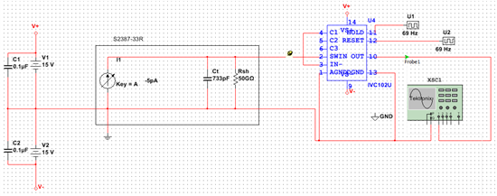
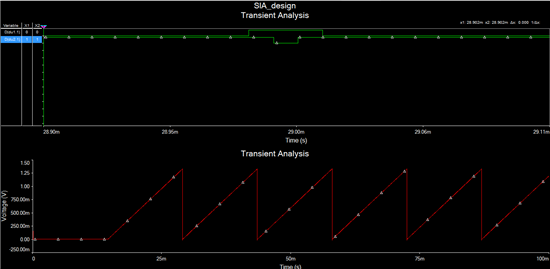
I decided to use the SWITCHED-INPUT MEASUREMENT TECNIQUE as described in the datasheet. The results look correct a priori. However, I am using a variable DC current in the input and the output is completely independent of that value. It is always a positive-ramp at Vo!!!!

I've tried different configurations, components. Thus, I am wondering if I am missunderstanding something, if the model in Multisim is incorrect or if this configuration is not suitable for this application.

PS. I attach the schematic and output plots!!!

  • Hello Javier,

    Tracing through your IVC102 schematic it does look as though you have the basic Switched-Input Measurement technique circuit set up correctly. The one thing that catches my eye is your input current source. Even though it show the generator connected such that current would flow into the pin 2 input, there is a negative sign before the 5 pA current (-5 pA). The current will then flow out of the pin. If Multisim follows the usual conventions, the IVC102 output would integrate to a positive voltage, instead of a negative voltage.

    Try changing the input current's sign and see if the output integrates as expected and as seen in data sheet Figure 3b.

    Regards, Thomas

    PA- Linear Applications Engineering

  • Hi Thomas,

    Thanks for your answer. However, as I commented above, I've been trying to change the value of the current from 5pA to -5pA. The results in the transient analysis are alwas the same as the one I show in the picture. I have also tried using a probe (just in case the settings were not correct) and it shows the same results (Vpp=1.35pA) independent on the input current.

    As you said, the schematic looks fine. Thus, I have no clue what is going on...

    Thanks again

    Javier Gorrono

    Higher Research Scientist (National Physical Laboratory)

  • Hello Javier,

    Can you send me the timing details for blocks U1 and U2. I am having difficulty determining the exact settings from your simulation's timing diagram.

    I plan to set your IVC102 circuit up in our TINA-TI Spice simulator and see if I can recreate your results. If there is a problem with the simulation model it should be duplicated in TINA.

    Regards, Thomas

    PA - Linear Applications Engineering

  • Sure Thomas,

    I wanted as a first attempt to follow a similar configuration from figure 3b in the IVC102 datasheet. The signal S1,S2 follow the same shape as in the figure.

    That means, S1 with f=69Hz, duty cycle=0.207% and delay= 0us. For S2 f=69Hz, duty cycle= 99.931% and delay= 14512'8us.

    Are the initial conditions a problem for the circuit? I don't think so but just in case...

    Anyway, let me know the result

    Thanks in advance

    Javier Gorrono

  • Hello Javier,

    I set up the IVC102 switched-input measurement circuit in our TINA Spice simulator. Although I didn't use your same timings for U1 and U2, I received the positive going integration slope as you did with a +5 pA input current - opposite of what is expected. Then, I increased the input current to +100 nA and found the integration slope was now negative at the output as it should be. Further testing revealed that the model produced the correct integrator output slope when the input current was +1 nA, or greater, and incorrect when the current was below that level. The integrator output slope was always positive for a negative input current - despite its level.

    I am going to contact our model group and explain the IVC102 model behavior we have observed to them. They may be able to determine why it is doing this and attempt to correct it.

    Regards, Thomas

    PA - Linear Applications Engineering


  • Hello Thomas,

    Thanks a lot. I've modelled the IVC102 using an OPA129 and switches and it provides a negative output as expected.

    I'll be waiting for the reply from your colleagues.

    Thanks again

    Javier Gorrono

    Higher Research Scientist - National Physical Laboratory

  • Hi there,

    I am having the same problem. I want to use a 10 pA current with the IVC102 in LTSpice but the output voltage does not get inverted. Moreover, the slope of the output voltage is significantly larger than it should be. I noticed that it stops functioning properly at 0.1 nA currents or smaller. Was your model group able to determine the problem and fix it?

    Please help. Thanks.
  • Hi Shiva,

    I realized when I saw your latest post that I hadn't received any update on the IVC102 model issue. I just sent a message to the group that works on models requesting an update. As soon as I hear back from them I'll let you know what I find. I apologize for the delays.

    Regards, Thomas

    PA - Linear Applications Engineering

  • I can confirm the same issue reported by Shiva and others, and using a slightly different setup in TINA-TI.


    Noteworthy perhaps are these remarks provided when you right-click on the IVC102 model and view the macro.  These notes apply to how you work the two internal switches, and using these to set the internal bias point properly when starting the simulation.


    Maybe these will be useful, but I don't believe they apply directly to the model failing to respond as described.

    IVC102M (switched integrator) MULTIPLE POLE/ZERO MACROMODEL
    *
    * REV. A  Created 5-30-96 BCB
    * REV.B  20 JUNE 97 NPA: MOVED LEGAL DISCLAIMER TO BEGINNING OF FILE
    *
    *
    * NOTES :
    *    1.  The transient time for the input to the switches (HOLD and
    *        RESET) should be programmed to 6V/usec.  
    *        Complying with this requirment will give you greater
    *        success in convergence during transient analysis and
    *        a more accurate simulation of the effect of the 200nsec
    *        switching speed of the actual switching transistors in
    *        the IVC102.  This is easily implemented with the PULSE
    *        command in Spice.  If your input signal to the switches
    *        is faster than recommended above, the R-C, low-pass filter
    *        on the input of the switch will slow the signal down some-
    *        what, however not enough to comply with the data sheet stated
    *        switching speeds of 200nsec.
    *    2.  To insure proper operation, always establish the initial
    *        bias point for the transient analysis with RESET and
    *        HOLD equal to the potential at COM
    *