This thread has been locked.

If you have a related question, please click the "Ask a related question" button in the top right corner. The newly created question will be automatically linked to this question.

LMP8603-Q1

Other Parts Discussed in Thread: LMP8603, LMP8603-Q1

Dear, Sir.

LMP8603 has "OFFSET" pin for bidirectional current sensing.

The output is 1/2 voltage applying the "OFFSET" is referenced to mid-rail voltage.

The datasheet indicates "OFFSET" pin tied to "VS" under such usage.


Is it no problem that "OFFSET" tied to another voltage source closed to "VS" voltage?

It could be utilized as output voltage offset adjustment if possible.

Is this kind of usage acceptable for LMP8603?

Best Regards,

  • I've moved this to the precision amplifier forum since they will be able to answer your question faster.

  • Hello Hideyuki,

    Yes. You can drive it from and external voltage.

    This is covered in the last paragraph of "Bidirectional Current Sensing" on page 19 of the LMP8603 datasheet, as well as the note at the bottom of that page:

    "When the offset pin is tied to the positive supply rail, the
    signal on the A1 and OUT pins is referenced to a mid-rail voltage which allows bidirectional current sensing.
    When the offset pin is connected to a voltage source, the output signal will be level shifted to that voltage divided
    by two. In principle, the output signal can be shifted to any voltage between 0 and V S /2 by applying twice that
    voltage from a low impedance source to the OFFSET pin."

    "(1)   The OFFSET pin has to be driven from a very low-impedance source (<10Ω). This is because the OFFSET pin internally connects
    directly to the resistive feedback networks of the two gain stages. When the OFFSET pin is driven from a relatively large impedance
    (e.g. a resistive divider between the supply rails) accuracy will decrease."

  • Dear, Paul-san. 

    Thank you for your good pointing. 

    I didn't notice the comment on the datasheet, Sorry. 

    I will refer that. Thanks again!!

    Beat Regards, 

    H. Sakai

  • Dear, Paul-san. 

    Please help me one more thing. 

    My customer is located Rs=2mOHM and monitoring +- 10A under bidirectional mode(Vs=5V).

    Around 0A current monitoring is significant for them, not max current. 

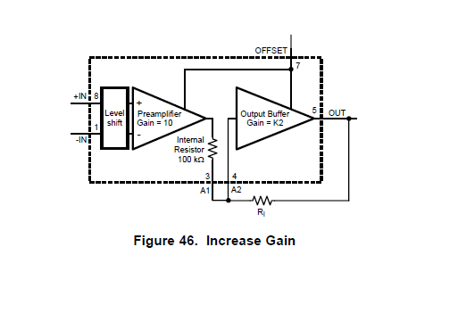
    Is it no problem that taking INCREASE GAIN(x2 ~ x2.5) method and scaling-up around 0A current

    zone even if the device output will be clipping? 

    Best Regards, 

  • Hello Hideyuki,

    "Clipping" will not hurt the device, so they can increase the gain for more resolution around zero, but at the expense of maximum resolution.

    It is possible to add a little additional gain by adding an external resistor. This technique is shown on pages 18-19 of the datasheet.

    Regards,

  • Dear, Paul-san. 

    I appreciate your teaching again, I will refer that. 

    Personally, LMP8603  will be so unique because it can be adjustable

    for OFFSET(using external power supply like tracker) & GAIN(using external potentiometer)

    ignoring thermal coefficient under bidirectional mode. 

    Best Regards, 

  • Dear, Paul-san. 

    Thank you for your teaching so many times. 

    Customer, Imasen will start the design applying LMP8603. It is totally depended on

    your teachings. Thanks again. 

    Sorry again, but Please help me one more time.

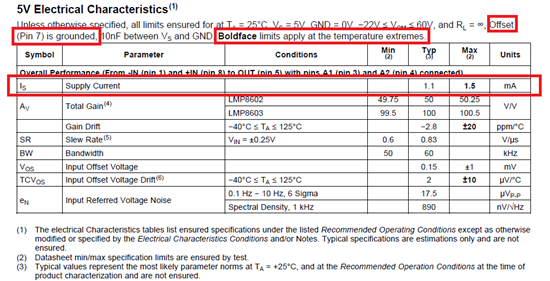
    1. They are asking about the current consumption under various temperature. 

        Max 1.5mA is defined on the datasheet. Is it under -40deg.C? 

    2. Tendency of  current consumption, under higher temperature such as 125deg.C, 

        current consumption become smaller than low temperature? 

    3. They want  to know the current consumption under Offset(Pin7) is connected to Vs. 

        The condition on datasheet is Offset(Pin7) is connected to GND. 

        How much is difference between Offset(Pin7) is connected to Vs & GND. 

        I tried to measure it using simulation model. It looks around 25uA sink on Offset(Pin7). 

        Please give me your advice. 

    Best Regards, 

  • Hello Hideyuki,

    I'll try to provide some feedback to your questions.

    1. The max 1.5mA supply current specified in the datasheet would cover the whole range of temperature from -40deg C to +125deg C.

    2. The tendency of the current consumption with respect to temperature is that the current is higher for +125deg C and is lower for -40deg C. This is all within the 1.5mA max specification.

    3. The Offset pin current is a bit tricky because the pin connects internally to the feedback networks of both gain stages of the LMP8603, making the Offset pin current dependent on the input signal. I measured the Offset pin current of a device with Vdd=5V, Vcm=2.5V and Vin=0mV and it results in about 130uA.

      As I mentioned, the Offset pin current is signal dependent. I measured that for an increase of 10mV at the input, the current decreases by 5 or 6 uA. A decrease of 10mV at the input results in an increase of the Offset pin current of 5 or 6 uA.

    I hope you find this information helpful.

    Best regards,

    Sergio

  • Dear, Sergio-san. 

    Thank you for your valuable and helpful information. 

    I will refer that, Thanks a lot!!

    Best Regards, 

  • Dear, Sergio-san. 

    Sorry again, but I would like to make sure just one simple thing. 

    Please give your advice.

    Question : 

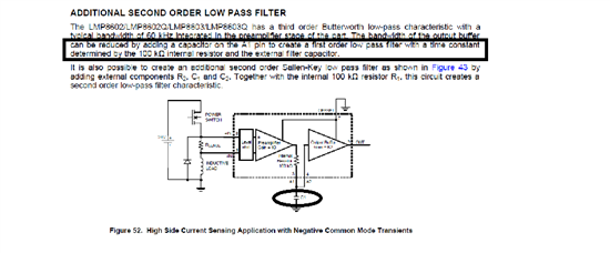
    According the datasheet, A capacitor between A1 & A2, It would work as a first order LPF with internal resistor. 

    I wonder If the LPF was not needed, immediate connection A1 & A2 without the capacitor is no problem?

    Is there any kind of reason to be might to put such capacitor? 

    Best Regards, 

  • Hello Hideyuki,

    It is possible to route the signal directly between A1 and A2... there is no problem with that.

    Adding the capacitor, as mentioned in the datasheet, introduces a low-pass filter in combination with the internal 100k ohm resistor. In situations where the full bandwidth of the LMP8603 is not required, this filter can be used to reduce the bandwidth, and as a result, filter the higher frequency noise content before the signal goes into the second stage (K2).

    Best regards,

    Sergio

  • Dear, Sergio-san. 

    Thank you for your detail explanation. 

    LMP8603-Q1 has the special usage like Increase Gain. 

    Under Increase Gain application circuit and add on a capacitor expecting LPF, A1 & A2, 

    Proper LPF performance can't be realized. Correct? 

    Best Regards, 

  • Hi Hideyuki,

    Using the model in a simulation, there is still a low-pass filter characteristic with the increased gain, but the location of the filter's pole is no longer determined only by the internal resistor and the external capacitor.

    The increased (AC) gain equation becomes like this:

    I am calling Cf the filter capacitor connected to A1. You will notice that the increased DC gain remains the same. By substituting 0 for "w" above, the resulting simplified equation is the same as equation 23 in the datasheet.

    The cutoff frequency of the low-pass filter can be approximated as:

    Divide w0 by 2pi to convert the frequency from radians to hertz.

    What value bandwidth and gain are you interested in using? The datasheet recommends not to exceed a factor of 2.5x in gain increase, but I don't have a way to determine if/how this limitation changes due to this configuration.

    Regards,

    Sergio

  • Dear, Sergio-san. 

    I am feeling a mount of gratitude for all of your valuable information. 

    It is so useful. Thanks a lot!!

    Best Regards,,