This thread has been locked.

If you have a related question, please click the "Ask a related question" button in the top right corner. The newly created question will be automatically linked to this question.

IA122

Other Parts Discussed in Thread: TLE2426, BUF634, INA122, INA326, REF2041, TINA-TI

I have a question about the REF pin. My impression is that if my signal is AC and I want to use a single supply, say 5V, I should put 2.5 volts DC on the ref pin. If this is correct, is it possible to put a TLE2426 with a BUF634 on the ref pin to supply the offset ? Also, does this imply that if a have an input signal which is pure AC, the zero of the output will be at 2.5V ?

  • Hello Bob,

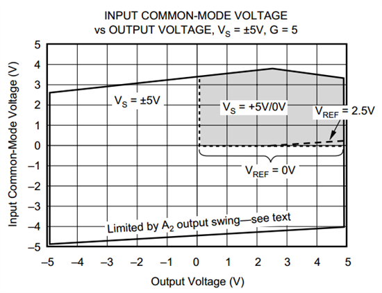
    You do not have to supply a reference voltage to use the INA122 with a single supply. Please refer to the following figure from the data sheet:

    As a matter of fact, providing a reference voltage of 2.5V actually reduces the output swing slightly for common-mode voltages less than ~0.2V.

    I'm concerned, however, that your input signal swings below ground. If that is the case, the device will not be in linear operation since the common-mode voltage range does not extend below ground. In addition, the output range does not extend below ground. If this is the case, I recommend either summing your ac signal with a dc voltage to ensure linear operation or you could consider the INA326.

    The INA326 uses a unique current-based topology that enables the common-mode to extend 20mV below the negative supply. The output, however, can only swing to within 75mV(min) of the negative supply. Therefore you should supply a sufficient reference voltage to ensure that the output range is not violated.

  • Hello Bob,

    I would like to add to my previous post. I want to make sure it's understood that while a reference voltage is not necessary for single supply operation, the output of the device is limited by the negative supply voltage. If your differential input is negative, the device will try to output a negative voltage. So, you will have to add a reference voltage to pedestal the output so you do not run into output swing limitations.

  • Thanks for both responses. I should describe the sensor I intend to use. It's a geophone (so a moving coil which responds to ground motion - specifically the velocity of ground motion, with an output of approximately .3V/cm/sec). As such, the output of the geophone is inherently AC, and the ground motion of most interest in this application is ~1-10 Hz. So the input voltage can be in the range ~ 30mV all the way to approximately 1.5 V.

    Please forgive my ignorance about the internals of instrument amplifiers ! If I'm using a single-sided supply voltage of 5 V, with the ac - signal I described, don't I have to hold both inputs at say 2.5 V above the amplifier ground in order to allow the first stage to handle the input voltage range ? You see, I'm confused about the behavior of the input stage of the instrument amplifier when it comes to the differential input, as far as +- voltage swings of the geophone are concerned. For example, do the two outputs from the geophone simply float, or are each of them tied to the amplifier ground ? If they don't float, then how does the input stage handle an ac -signal in the presence of the +- swings ? It seems from your second answer that the differential input can float and still handle an ac - input, but that the output would then potentially try to swing negative in the absence of a bias voltage via the REF pin.

    On the other side, it seems if I bias the inputs properly, I don't need to fool with the REF pin, as the output should be riding on 2.5 V DC. Is this correct ? You see, my ultimate aim is to feed this output into a 0-5 V ADC.

    Sorry to be so long-winded and ignorant, but I hope this clarifies to some extent my inexperience and confusion.

  • Hello Bob,

    The purpose of an instrumentation amplifier is to amplify the differential signal at the
    inputs [(Vin+)-(Vin-)] and reject the common-mode signal. The output stage adds the reference voltage.
    Here is a generic transfer function of an instrumentation amplifier:

    Vout=(Vdifferential*Gain)+Vreference

    You see that ideally there is no amplification of the common-mode input signal.

    At the same time, however, the input common-mode signal must meet the data sheet
    requirements. For the INA122 with a single 5V supply the range is 0V to 3.4V.

    However, I believe your input signal is actually +/-30mV to +/-1.5V.

    If so, let's examine the case for a differential signal of -30mV and Vreference=0V with a
    common-mode voltage at ground. The problem is two fold. First, the input signal goes 30mV
    below ground, which is not within the range mentioned above (0V to 3.4V). Secondly, let's
    calculate the output voltage with the ideal equation above:

    Vout=(-30mV*G)+0=-30mV*G

    This also violates the output swing limitation of the INA122, which is actually 150mV (min)  above
    the negative supply voltage (ground in this case).

    If my assumption about your input signal above is correct, you need to add a common-mode
    voltage to the ac signal to ensure it's within the proper range of the device. Similarly you should add a reference voltage to ensure that the output range is not violated.

    I hope this helps!

  • Hi Pete,

    Again thanks. I think this does get to the heart of my issue. The input voltage swings were +/- 30 mV to +/- 1.5 V. If I understand correctly, the input to the instrument amp with a single supply behaves like an ordinary op amp in the sense that a negative voltage at input with a single supply will force the input below ground, and therefore that the input must be biased sufficiently above ground to prevent a negative input voltage, and that the output (REF pin) must be biased above ground because the amplifier also rejects the common mode DC bias at the input. Do I understand this correctly ?

    Second, could I use a TLE2426/BUF634 combination to provide the necessary bias voltages for input and output ?

    Thanks for your patience.

  • Hello Bob,

    Sorry for the delay.

    Please see the attached TINA-TI simulation.  I believe it's ultimately what you're trying to do with the INA, TLE, and BUF devices.  There are a variety of ways to generate the amplifier supply and common-mode/reference voltage (including the TLE device).  However, in the simulation I used one of our newer references, the REF2041.  Nonetheless the idea is the same.

    I hope this helps.

    bob.TSC