This thread has been locked.

If you have a related question, please click the "Ask a related question" button in the top right corner. The newly created question will be automatically linked to this question.

Quad OPA4209 heat problem

Other Parts Discussed in Thread: REF2925, OPA4209, REF3125

Hello,

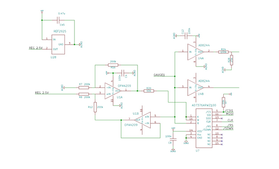
I'm using quad OPA4209 as current sources, as in the schematics below. I have two same channels, using the same voltage reference REF2925. The digital potentiometer is set to 75 kOhms, making the total resistance between PIN1 and PIN5 of 125 kOhms. The potential between these PIns is set by the REF2925, and is equal to 2.5V, allowing 20 µA flowing throw a resistive load (100 kOhms for example) plugged between GAUGE1 and GND. So, the potential of GAUGE1 is: 20µA*100kOhms = 2V. 

Despite goods voltages levels, the OPA4209 heat very quickly... I don't find the issue...

I've already try to short the input of potentimeter, but the heat problem still happen...

Thanks for help!

Arnaud

  • user4156923,

    There are a few questions that we need answered before we give you a good response.

    1. What power are you applying to the amplifier?
    2. What is the exact part number that you are using? ( I am looking for the package that the amplifier is housed in)
    3. What is the ambient temperature when you are measuring with this amplifiers temperature?
    4. What is the temperature of this amplifier (above ambient)?

    Please note that the queiscent current for each amplifier is typically 2.2 mA. For the quad, OPA4209, the quiescent current would be 8.8 mA.

  • Hello Bonnie,

    thanks for your answer.

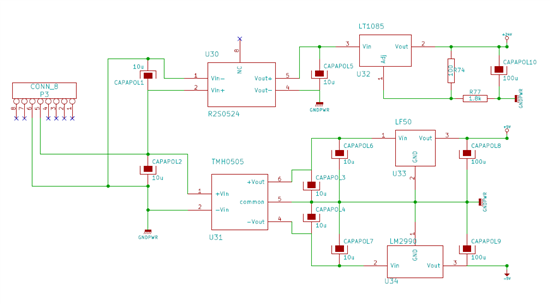
    1. I apply appproximatively 23V thanks to a 5V/24V convertor (RS20524-Recom), rated for a 83 mA output current, and a low drop out voltage regulator (LT1085). On the 24V supply line, i have 3 quad OPA, 6 digital potentiometers (AD7376), and 3 quad buffers (AD8244), making a total supply current about: (3*8.8)+(6*2)+(3*0.25) = 40mA. I give you the supply schematics below.

    2. The part used is AIPW, so a TSSOP package.

    3. I make the measurements at room temperature, about 23°C.

    4. The 3 OPA raised a temperature about 100°C

  • user4165923,

    I am still not sure what power supply you are using for your OPA4209 amplifiers. Please elaborate.

    If I were to estimate the temperature of the OPA4209 with a 23V supply I would calcultate the estimate increase in temperature (form ambient) as:

    delta temp = theta-ja * Vsupply * Iq

    delta temp = 112.8 C/W * 23 V * (2.2 mA *4)

    delta temp = 22 C

    So if the chip is not driving any resistors, I would estimate your device temperature to be 22 C + 23 C or approximately 45 C.

    A few further questions:

    • Are you driving any load resistors?
    • Are you measuring the temperature of the OPA4209 with the circuit in a quiescent state?

    Please send the circuit diagram with the OPA4209 chips.

  • Hello Bonnie,

    The PCB is powered by 5V from USB (Laptop).

    For debugging, i was driving 100 kOhms resistors.

    I have found that there is an oscillation (about 1MHz - hundred of millivolts pic to pic) on the output PIN of the REF2925. It stabilise if i force the REF2925 output to deliver some current by adding a 10 kOhms resistors between output pin and GND. Work well with 100 kOhms resistors load.

    What happen if the load resistors are larger, let's say 0.5-1MOhms? The feedback voltage is higher than 2.5V, and i think the output of REF2925 isn't able to deliver clean 2.5V regulated voltage. 

    I give you the entire schematic below. 

    Thanks!

    0028.6X-simple analog front end - high voltage.pdf

  • user4165923,

    This is a very interesting fact that you have brought up. It appears that the REF2925 ocsillation is causing higher currents in the OPA4209. This is possible.

    I was examing your circuit diagram and noticed that the by pass capacitor on the REF2925 is 0.47 uF. In the REF2925 data sheet, a 1 to 10 uF capacitor is recommended. Is it possible for you to change this bypass value to 4.7 uF?

  • Thanks for your answer Bonnie.

    I've seen in REF2925 datasheet (page 8) that supply bypass capacitor recommended is 0.47 µF. I haven't found any traces of 1 to 10 µF bypass capacitor in the datasheet!

    But anyway, the trick you recommended works well because with a 4.7 µF supply bypass capcitor, the oscillation goes away!

    Do you have an explication for this behavior, and why the oscillation dissapear too if i put a 10kOhms resistor betwwen output pin of REF2925 and ground ??

  • You can find these types of capacitors on page 9, figure 6 of the data sheet.

    Here is another angle to look at. Resistive loading of the output stage, increases the current in the output transistors and thus lowers its output impedance - thus improves stability.  However, looking at your schematic, especially the input voltage range on pin 5 of U1B, I would be concerned about the violation of the input common-mode voltage of OPA4209 which extends only 1.5V from either rail.  Also, if this input voltage gets above 2.5V, REF2925 would have to be able to sink current, which it CANNOT (it’s an LDO type reference) - this would result in the voltage reference on REF2925 output rising above 2.5V resulting in unstable operation.

  • Ok, thanks for precisions.

    About capacitors, i thought you were speaking about supply bypass (input pin of REF2925), and not output pin, like it's written on the page 9 of the datasheet...

    About the "sinking problem" of REF2925, is it possible to bufferize it to make it "sinkable" (adding a follower stage after output pin)?

    Or do you have other component reference able to sink current ?

  • Right you are about the capacitance.

    The REF2925 does not a a 'sinking problem'. I would not recommend using a buffer at the output of this device. the buffer will solve the problem but it may add unwanted errors into yoru signal path. I suggest you look at the REF3125 as an alternative to the REF2925..

  • About the term 'sinking problem', i was incriminating my own design, of course, not the REF2925 !

    Anyway, thanks a lot for help and for the REF3125, wich i will try asap.

    Arnaud

  • I understand your dilemma. I am hoping that the REF3125 solves your problem. It seems to be a better reference as well.