This thread has been locked.

If you have a related question, please click the "Ask a related question" button in the top right corner. The newly created question will be automatically linked to this question.

Reading 4-20mA Sensors

Other Parts Discussed in Thread: ADS1115, INA332, INA3221

Hi,

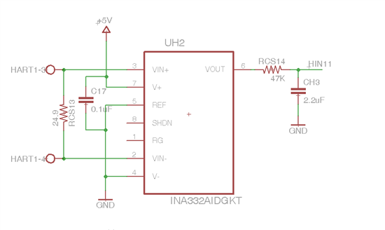
I need to read 6 x 4-20mA sensors. My current design utilize Instrumentation Amplifier TI INA332 and RC filter to eliminate the digital HART signal that is coming from the sensors and TI ADS1115 16 bit delta-sigma ADC. As shown in the following diagram.

I've got concerned when Ed Mullins mentioned in TechDay that the InAmp should be powered with the same voltage of Vbus. Could anyone please elaborate if this would be a problem for my circuit. Because to my understanding the voltage across RCS13 will not exceed 0.5V and after amplification it will be less that 2.5V.

I would like to hear opinion about using Current Shunt Monitors like INA3221 (triple channel I2C CSM) to perform the task. Especially in regard to the filtering of the digital signal. Or any other design that would be lower in cost or more reliable.

Thanks,

Edd


EDIT: the image was re-uploaded

  • Hi Edd,

    For some reason I cannot see the image you embedded in your post...if you can either repost it or just email me directly...my comment regarding the Instrumentation Amplifiers was that the inputs have to be within the power supply voltage of the device...perhaps your curcuit is just fine the way you have it, but I can't see it.

  • Good morning Ed,

    I've re-uploaded the image in the original post, I hope you can see it now!

    By the way, thanks for the brilliant lecture "Current Sensing Solutions from Texas Instruments" on TI Tech Days in Anaheim. I'm sorry if I misunderstand your point.

  • Hi Edd,

    Thanks for attending and your nice comments...from your schematic I cannot be certain that your input pins are always biased within the common mode input range of the INA332...when using a 5V single supply system the input common mode range for the INA332 is given as:

    If your inputs are always between the min and max you will be OK.  Are the inputs always going to be within the range?

  • I'm afraid, not. The current passing through RCS13 will be between 0-25mA, which means it is between 0 and 0.6225V. This render the output not usable?

    What do you suggest to use instead? and what about Current Shunt Monitors with digital output such as INA3221? do you think it would work?