This thread has been locked.

If you have a related question, please click the "Ask a related question" button in the top right corner. The newly created question will be automatically linked to this question.

Recording Plant bio-signals

Other Parts Discussed in Thread: INA826, INA333, REF3225, INA116, INA111, TLE2426, INA128

Hello,


we are working in a project to record plant electrical activity e.g.  http://www.ncbi.nlm.nih.gov/pmc/articles/PMC158572/ 

Ideally, this should be similar to ECG, provided that the characteristics of the electrical signals generated by plants are not yet clear and iare likely not quasi-periodic as in ECG. However, as a starting point we are experimenting with "standard" instrumentation amplifiers for ECG.


In particular we are now experimenting with the INA826 and a basic version of the ECG schematics in figure 67 of the datasheet.


First of all I would really appreciate any sugestion on possible alternative solutions (e.g. te INA 333), then I have few very basic questions:


1) Provided that we are not now worried about possible injuries to the plant, Can we remove all the capacitors and resistance from the electrodes to the inputs of the INA 826?

2) Can we also remove the RL driven circuitary? In this case, where should we  connect the Refernce Electrode?

3) In the first version, just to have a rough idea of the signal, I think we can also remove the integrating amplifier  used to remove the DC offset ... we can plug it later to improve the quality of the signal


With 1,2 and 3 in place, we should have a very basic configuration to start our invetigation. Do you consider it a good starting point?


Finally another clarification. In the datasheets of the instrumentation amplifiers,  it  is always suggested to connect both the inputs to the ground with two proper resistors (one for each channel) to provide a return path for the current bias. However, in almost all the schematics for ECG I checked out I saw such resistors only very few time. Why?

Thanks in advance, Andrea

  • Hello Andrea,

    To be honest we have no experience measuring the electrical activity of plants. So I will answer your questions as best I can.

    1) If you remove all resistors and capacitors you will also remove the signal filtering. So, if you don't expect the plant's biopotentials to be noisy, you can remove all passives on the input pins.

    2) It is hard to me to know if you need a RLD circuit or not since I'm not sure if you're expecting much 50/60Hz noise and I do not know the model for the plant electrodes. That said, I recommend trying to obtain signals without the RLD circuit at first. If possible, be sure to use the largest dual supplies available depending on your device (e.g. if you can use the INA826, try +/-15V supplies...use +/-2.5V supplies with the INA333). For more details on RLD, please see the "Design Considerations" presentation at the following link:

    http://e2e.ti.com/support/amplifiers/precision_amplifiers/w/design_notes/2437.ecg-heart-signal-acquisition.aspx

    3) I agree. I would keep the initial circuit as simple as possible at first and then add additional circuitry as needed.

    Your final question about input bias current return path...it depends on the plant's impedance. I highly doubt you need those resistors. You likely saw such resistors in ECG schematics if the inputs were ac coupled.

    I hope this helps.


  • Thanks a lot Pete.

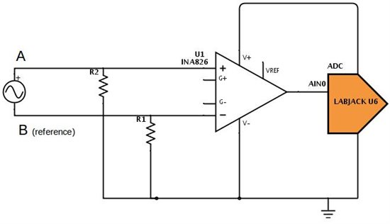
    In the meanwhile I did some experiments summarised in the report in attachment. with the very basic schematic that follows


    I have a fundamental question to answer. The main goal we have is  to measure the variation of a signal in the plant at point A  with respect to a reference in the plant at point B.

    A and B are ungrounded signal sources

    In principle I would plug A into the + of the instrumentation amplifier and B into the -

    However, according to http://www.planetanalog.com/document.asp?doc_id=527518

    ... an in amp cannot measure floating voltages. This includes anything that is not referenced to ground ...”

    So if I'm not wrong the purpose of the resistors between + - and the GND (see Figure 1 in the report in attachment) is   to provide a reference. (see also http://www.ni.com/white-paper/3394/en/ )

    Am' I right? Otherwise, do I have to explicitly connect a third electrode linking the GND of the ampli with the plant to provide a "common ground"?

    Regards, Andrea


    P.S. I'm now using an INA826 single supply at 5 volts and a ref at 2.5, but I'll try the INA333 according to your suggestion

    report2.pdf
  • Hello Andrea,

    Thanks for the clarification...I pictured the plant in the ground.

    While your circuit now has an input bias current return path (though I don't think the impedance of a plant is very large), I'm worried about the common-mode voltage of your input signal.

    Therefore I recommend biasing the plant to mid-supply (2.5V) using one of your 'needle electrodes' since you're operating with a single 5V supply. Then you no longer require R1 and R2. In addition, connect node B and Vref to 2.5V as well. Then the output of your instrumentation amplifier should be Vout=Gain*(VA-2.5)+2.5V. You can then set the gain accordingly so that your output swing from ~100mV to ~4.9V (assuming you're now using the INA333).

  • Hello Pete


    not sure I have completely understood.... are you suggesting the following schema? ... or the introduction of a third, electrode above a and B, only to bias the plant

    Furthermore, right now I'm using the ref 3225 to have a ref at 2.5V ... can it be used also to bias the plant?


    I have ordered the INA333, but I'm still working with the INA826


    Regards, Andrea

  • Hello Andrea,

    I was thinking of a 3rd electrode placed immediately adjacent to B, but the schematic as drawn may work as well. Yes, try using the REF3225 to drive the 2.5V node. The INA826 should work in this configuration as well.

  • Hello Pete

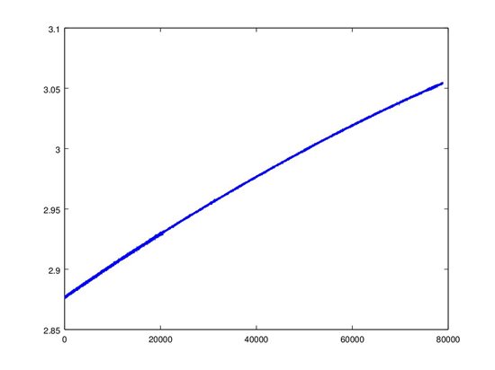
    I tried the configuration in the post of Oct 28 2014 16:43 PM but I got the following results

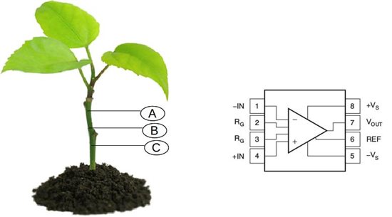
    and the signal keep growing ... so may be I need the third electrode, but I want to be completely sure I have understood the configuration you are suggesting. Can you please be so kind the explicitly indicate me the connection according to the following diagram? ... I'm really sorry to bother you.

    You have thre electrode A,B and C and the 8 pins of the Instrumentation amplifier, an INA826

    Right now

    1) Pin 6  is +2.5 V (by a REF3225)

    2) Pin 5 is GND provided by the DAQ, a labjack U6 http://labjack.com/u6

    3) Pin 8 is +5V provided by the DAQ

    4) Pin 7 is connected to the AIN0 (the analog input) of the DAQ

    5) Pin 2 and Pin 3 are not connected (i.e. GAIN = 1)

    It remains to connect the pins 1 and 4 and the electrodes.

    I also kindly ask you to provide any further recommendatino on the placement of the electrodes (e.g. B close to C)

    Thanks a lot, Andrea

  • Hello Andrea,

    Connect pin 4 to A. Insert both needle probes B and C together at the base of your plant. Then connect pin 1 and needle probes B and C to 2.5V (either lab supply or REF3225).

    You will need to add gain to your signal. I am unsure of how much, though, since I don't know the magnitude of typical plant biopotentials. If they are of the magnitude +/-1mV, you could set the INA in a gain of 1000V/V. The output would then swing from 1.5V to 3.5V (negative biopotentials would be represented by voltage from 1.5V to 2.5V and positive potentials would be represented by 2.5V to 3.5V).

    Finally, you will also need to place a decoupling capacitor on the supply pin as described in the data sheet.

  • Andrea and Pete,

    I suspect that the slow change in output voltage may be due to polarization of the electrodes created by the input bias current of the INA826. I suggest changing to a FET-input instrumentation amplifier to greatly reducing the input bias current. INA111 or INA116 might be candidates.

    The selection of electrode material may also be very important. Chemical reaction between organic compounds and the electrode may be creating a weak electro-chemical cell with a slowly changing voltage.

    Regards-- Bruce

  • Hi Pete

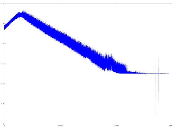
    I tried the configuration you suggested and I got the following result

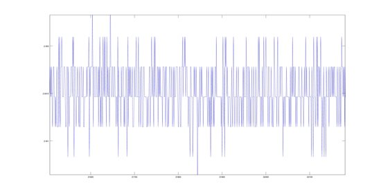
    It seems that after a "long period of settling", the difference between VIN+ and  VIN- is zero  (2.5V is the reference) ... observe that in the last part of the graph only signals above 2.5 are recorded, wile everything below is cut off.  In the following figure a zoom of the last part of the signal.

    Any suggestion on how to preceed?


    Thanks a lot for your kind support, Andrea

  • Hi Bruce

    thank you for the support. I ordered the INA333. Do you think it is a good candidate to make a try?

    The input bias current of the INA111 is +-20pA max

    The input bias current of INA333 is an order of magnitude bigger


    In any case, in view of the suspect on the input bias, do tou suggest to introduce a resistor between VIN+ and GND and VIN- and GND?

    Furthermore, if I'm not wrong,  the INA 111 requires a dual supply. Any suggestino to implement a good quality dual supply. I made a try with an LM7805 and a TL2426, but it seems to me pretty noisy.

    In my opinion, the paper at the following link is the most significant reference of a successfull experience in recording signals generated by plants  ... notice that it refers to an INA116

    http://link.springer.com/article/10.1007%2Fs10535-010-0032-0


    Regards and thanks a lot, Andrea

  • Andrea,

    I think the INA111 would be a better choice. I do not recommend that biasing resistors be used on the inputs to ground. If you have made a reasonably good electrical connection to the plant, input bias current will be supplied through conductivity of the plant. A large, drifting output voltage can then be used as an indication that there is poor electrode connection or poor conductivity though the plant. Such largely varying signals are unlikely to indicate that the plant is deep in thought. :)

    These electrode and contact issues are very important as it is easy to create the appearance of biologic signals that are actually measurement artifacts.

    I believe that you are referring to the TLE2426, not TL2426. I think it would be better to make a true dual supply. LM7905 is the matching negative version of the LM7805. Actually, for the INA111, I would recommend higher voltage-- LM7812 and LM7912.

    Regards--  Bruce

  • Thank you Bruce


    I'll try to make the circuit next week and provide you a feedback ...


    I would like a further clarification: it seems that a major issue in plants  is the input current bias. Is this an indication that the impedance of the plant is significantly higher than that in human body?

    Regards, Andrea

  • Andrea,

    Yes, I believe that the impedance of electrodes placed on a plant could be quite high. It could vary widely depending on the type of plant (succulent vs. hardwood sapling, for example). Also, much could depend on the method of attachment of the electrode, affecting the impedance of the electrode contact itself.

    The point of low input bias current is to minimize artifacts due to current flowing through the contact impedance and plant impedance. Your circuit is attempting to measure bio-potentials (voltages). You don't want to confuse this with unintended measurement of the plant or electrode impedances. That might be interesting, too, but should use a very different circuit.

    The same issues can occur when measuring human bio-potentials, especially with dry electrodes. ECG signals, however, are well-studied and clearly periodic. It's comparatively easy to see when you have contact resistance artifacts.

    Regards--  Bruce

  • Dear Bruce


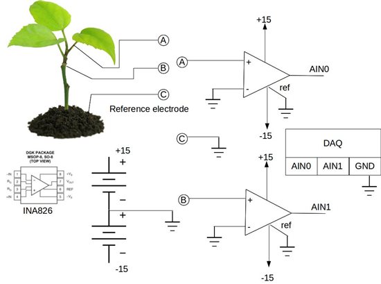
    the configuration in the following picture seems to work pretty well to study the signal propagation... we are improving.

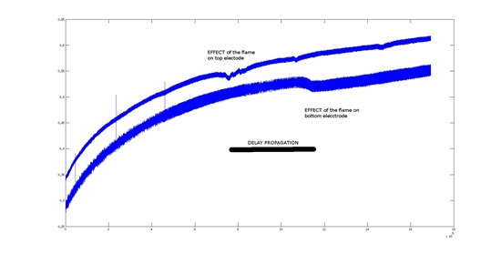
    The result of a gentle flame applied to a leaf is shown in the following picture (with a low pass filter at 40 Hz the signal is sharper)


    We are also experimenting with Ag electrodes vs Iron ... Ag is more stable, but further experiments are needed. The electrode in the soil is graphite (it is made from a pencil)

    In the meanwhile I also received the INA116 and INA111 and thus I will try also those devices.


    Thanks a lot for your kind support and I'll keeo you informed.

    Andrea

  • Andrea,

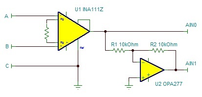
    I see some potential issues in the most recent circuit diagram you have posted. It is better to use a single instrumentation amplifier to make this type of differential measurement. I'm not sure why you are trying to use two INAs. It's not clear whether you are using these amplifies in G=1 (no gain-set resistor). If you use a larger gain (which may be required once you eliminate bias current errors) it is especially important to make this change. Your circuit will greatly degrade the common-mode rejection of the circuit.

    Here is what I recommend:

    This circuit can be used without a gain-set resistor (instrumentation amp in G=1), or you can add a resistor for higher gain if needed. I have not shown power supplies but the same +/-15V supply for both the INA and op amp are good. You have not explained what you are using for an A/D converter. This circuit provides complementary outputs. If no gain-set resistor is used, the gain at the differential outputs is 2. If your A/D converter can accept a single-ended input signal, the op amp circuit is not required--just use the INA's output.

    Both your circuit and mine requires that the A/D input(s) can convert accurately with negative input voltage.

    Regards--  Bruce


  • Hi Bruce,

    not sure I have understood your circuit... just to recap, the main purpose of the ciruit is to measure how the signal propagates along the plant with respect to a common reference C.

    To make clear the point, assuming that the signal is propagating from the top (A) to the bottom (B) , I expect that at time t_0 I will see something at A (i.e. A-C), then after I while at t_0+tau (the propagation of the signal should be cm/sec) I will see the "same signal" attenuated at B (i.e. B-C).

    Beeing C the reference should be "neutral", namely not affected by the propagation of the signal.


    A-C and B-C are finally provided in input to an A/D single ended, respectively AIN0 and AIN1, in order to see the propagation (as in the picture in the previous post)

    It is not clear to me that your circuit will allow us to follow the signal propagation... sorry for the trivial questions:

    a) By complementary outputs you mean A-C and B-C?

    b) the "square" at the output of the INA111 is the feedback, correct?


    Regards ... and thank you for your patience!

    Andrea

  • Hi Andrea,

    Okay, I understand your goal now. I'm sorry I confused the discussion. One of your earlier diagrams showed a single INA measuring the differential voltage between A and B so I got off on that track. This older diagram (posted Oct 28) would not support your desired measurement.

    Your latest diagram should work okay.It measures point A and point B, each with respect to the common ground point C. This type of measurement would not require an INA but could be done with two op amps (another reason I was on the wrong track). Still, your latest INA circuit will work.

    Other points I made regarding use of a FET-input amplifiers for low input bias current remains true. The INA111 or INA128 type INAs would be preferred to the INA826.

    Regards-- Bruce

  • hi Andrea
    even i am working on the same project that you are working its really amazing topic and glad to meet you here
    well coming to the point actually i am just in the beginning stage and have number of doubts regarding this, here they are
    1. why exactly are you using labjack DAQ system as per as i know DAQ system is a one which converts the physical parameters to electrical signals and then convert it to the digital signals .when we are measuring the voltage why do we need DAQ we can make use of ADC
    2. can needle electrodes be substituted with something else because i am just worried about the cost each electrode costs me 6000 bugs .
    3. we also need the filters to avoid the surrounding noise , but there is no filter in your circuit
    and sorry to bother you ..... please do post if any software simulated circuits you have

    thanking you
    regards
    nikhil s patil
    nikhilspatil321@gmail.com