This thread has been locked.

If you have a related question, please click the "Ask a related question" button in the top right corner. The newly created question will be automatically linked to this question.

INA326 for High side current sensing - 1uA to 150mA

Other Parts Discussed in Thread: INA326, INA138, TIPD135, INA327, TIPD104, INA225, TINA-TI, OPA313, OPA330, LM7705, TIPD129, ADS1015, TIPD128

Hi,

Need to do current measurement  from 3.3V to the load. Current will be  either in 0-100uA range or in 0-150mA range. Board has only 3.3V power. Resolution needed is 1uA / 1mA in each range.

Planning to use INA326 with  the configuration mentioned in Figure 8 of datasheet http://e2e.ti.com/support/amplifiers/precision_amplifiers/f/14.aspx?pi73417=5  (with 3.3V power Supply).  and use an 18 or 24 bit Del Sigma ADC at the o/p of INA326.

Am  I using the right  device for this application ?

Is there an accurate gain switching method for  INA326 using analog switches  so that I will get higher voltage o/p in 0 to 100 uA range and hence use a low resolution ADC?

Thanks in advance for the support on this.

Regards,

Anil

  • Nilesh,

    I would not recommend the INA138 for current sensing under 150mA.  I would suggest a true instrumentation amplifier.

    There was a very similar discussion at http://e2e.ti.com/support/amplifiers/current-shunt-monitors/f/931/p/339862/1187612.aspx#1187612 where the customer wanted to use the INA138 to measure very small currents but was discouraged from trying to do so, and some other options were presented.  The best one, in my opinion, is the TI Design TIPD135 that uses a PGA to measure current in almost exactly the range you are looking for with very good accuracy.  I strongly suggest you review it.

    In general, current shunt monitors are intended for larger currents, I would say 500mA to tens of Amps, maybe more.  This is primarily due to the design of the front end being very different from op amps and true instrumentation amplifiers.  The front end is designed in such a way that it is powered by the input bias currents, causing them to be much higher than usual for a true INA or op-amp, but also allows for the common mode voltage to exceed the supply.  Also, the draw of the bias current at 1uA will significantly exceed the signal itself, which is likely more problematic than the gain and offset error caused by the mismatch of input bias currents.

    Let me know how else I can assist.

    Jason Bridgmon

  • Hi Jason,


    Can we use INA327 (http://www.ti.com/lit/ds/symlink/ina327.pdf) for sensing current from 1uA to 100uA and 1mA to 200mA. in the datasheet figure8 shows the current sense application. can i give 100ohm for measuring 1uA and low Rs for measuring 1mA?

    Thanks

    Vinay

  • Hi jason,

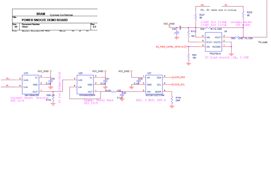
    We updated our circuit to use INA326.

    Can you review the attached schematics and let me know i can go ahead with this modification to measure the current ranges of 1mA - 150mA and  1uA to 100uA?

    Regards,

    nilesh

    uA TO mA CURRENT MEASUREMENT FOR REVIEW _20141201_A0.pdf
  • Hello Anil,

    Please take a look at TIPD104. Even though the design is for low-side sensing, it does implement gain-switching with the INA326.

  • Thanks a lot Pete Semig.

    Our team  has completed the schematic with INA326 .  It is  uploaded at  current shunt amplifier discussion forum as part of original discussion on this topic. Would  be great if you can have a look at that and comment.

    Link for the  discussion where  our latest schematic is posted  is  ( on Dec 01 by Nilesh)

    http://e2e.ti.com/support/amplifiers/current-shunt-monitors/f/931/p/384487/1356471.aspx#1356471

    Regards,

    Anil

  • Hello Anil,

    I have been on vacation and am looking at it right now.  I will get back with you shortly.

  • That is fine Pete Semig.

    Regards,

    Anil

  • Hello Nilesh,

    Measuring such a large load current range is challenging given that you only appear to have a single 3.3V supply. There are more than 5 decades of load current from 1uA to 150mA. Therefore I understand the desire to use multiple instrumentation amplifiers and sense resistors in the solution.

    While the mathematics appear to work out okay for this design (but please be aware that the output voltages for 1uA and 1mA are 20mV and 13.6mV, respectively, which are only slightly above the typical value in the data sheet and may not represent a very robust design), I recommend switching the gain of the instrumentation amplifier instead of using multiple sense resistors. In other words, the less you disturb the load current with sense resistors and FET switches, the better.

    Therefore I recommend evaluating a solution similar to the one I used in TIPD104, which uses a switch to change the gain of one INA326 instead of using multiple sense resistors and multiple INA devices.

    Also, I see in the notes of your schematic that you intend to test this design using a protoboard. Please note that the INA326 is very sensitive to parasitic capacitances on the gain setting pins of the device. Therefore I recommend building a prototype PCB instead of using a protoboard.

  • Hi,

    In my project I am trying to sense two different current ranges.

    • 1uA to 100uA
    • 1mA to 150mA

    We tried using INA138 and two sets of Shunt resistor ( 1KOhm for uA range and 0.4 Ohm for mA range)

    Is this the best solution for the requirement?

    Can I use INA225 or some other device?

    Regards,

    Nilesh

    Cypress Semicondutors

  • Hello Anil,

    I have posted my response to Nilesh's post at the following location:

    http://e2e.ti.com/support/amplifiers/current-shunt-monitors/f/931/p/384487/1361976.aspx#1361976

    Since these posts are related to the same topic, I will merge them together.

  • Thanks Pete Semig for the detailed review and response.

    Since 0.68 ohms is the max sense resistor we could use ( to limit 0.1V drop at 150 mA) , drop across the sense resistor when load current  is 1 uA will be only 0.68 uV.    

    Looking at the  input offset of  INA326 (100 uV max ) , thought better to keep the minimum signal amplitude to be measured above the  input offset voltage and hence kept the option of switching sense resistor. With this will get 1mV voltage drop across sense resistor 1K  when load current is 1uA ( min load current to be measured).

    Do you think , keeping  a fixed load sense resistor of  0.68 ohms and  amplifying 0.68uV will work fine with INA326 ?  or should  we switch both - i.e. sense resistor and gain resistor to take care of  input offset of 0.1mV and min typ output swing of  10mV?  

    We are going for a multi layer prototype board .

    Thanks & Regards,

    Anil

  • To clarify on proto board/pcb >> we are designing and fabricating a multilayer PCB and assemble the components for prototype. 

    Regards,

    Anil

  • Hi Pete Semig,

    Used TINA-TI simulation  tool ( was not  aware of such an excellent tool !!) and  simulated the  circuit both in uA and mA range. At the lower current side, as you mentioned , o/p was not  so linear.

    Added  a 0.6V Ref source at one end of R2. With this getting good linearity  even at very low currents.

    Since ADC chosen has  2 differential input , do not think I will loose any dynamic range. (btw, accurate 8 bits  is what I really need).

    Uploading  the sim results here. Would be great if you can look at it and comment.

    8737.uA to mA Measurement - Simulation results _A1.pdf

    Regards,

    Anil

  • Hello Anil,

    Providing a 0.6V reference is a good idea. However, the one you suggest has just 1% initial accuracy. I assume you would like better performance.

    Therefore I see a couple options. First, you could simply divide down your 3.3V supply and buffer it with an op amp (e.g. OPA313). The OPA313 is 1/2 the cost of the 0.6V reference. If you want better offset voltage, you could consider the OPA330, but it will cost more. In bulk, 0.1% resistors are reasonably priced. Finally, you could then set the reference voltage to nearly anything you want (I suggest 100mV).

    Another option is to use the LM7705 for the V- supply instead of the 0.6V reference. To understand how this would work, please take a look at TIPD129.

  • Hi Pete Semig,

    Since  I am using a differential input ADC and voltage drop 'across'  R2  will be measured, hope the absolute accuracy of  the reference  does not matter ?

    Since OPA313 is a cheaper option than Ref , as you suggested , will use a potential divider ( set  to ~ 0.1V  ) , buffer it with OPA313 and connect to R2 end. Both the ends of R2 will be given as differential input to the ADC. 

    Liked  LM7705 idea. Simulation  with that shows  slightly noisy o/p (in mV ).  

    Will go ahead with OPA313 for offsetting output swing.

    Thanks a lot Pete Semig and the TI team for  you support on this.   

    Regards,

    Anil

  • Hello Anil,

    While the ADC you're using can be configured for a differential measurement, you're not using it in that manner.

    Though I don't support ADCs, I will help the best I can. After looking at the ADS1015 data sheet Figure 8, it looks to me like the output of the PGA (which is differential-in, differential-out) is (V(AIN0)-V(AIN1))*PGAgain. Since you have AIN1 (and AIN3) connected to ground, the equation simplifies to V(AIN0)*PGAgain. The voltage at AIN0 is the output of the INA, which is ideally Vshunt*Gina+Vref. Therefore the ADC will convert a voltage that depends on Vref, so the accuracy of Vref is important.

    Please note that by grounding AIN1 and AIN3, you're only using 1/2 of the ADC codes available to you. Please refer to Figure 13 in the ADS1015 data sheet. You will see that in order to use codes 0x8000 to 0x0000, the input voltage (AINp-AINn, or AIN0-AIN1) must be negative. Since you connect AIN1 to ground, this result can never be negative.

    One solution is to provide another reference voltage at the middle of your input voltage range to AIN1 and AIN3. For example, let's say the output of your INA is 0V to 2V. If you connect 1V to AIN1, you will utilize codes 0x8000 to 0x0000 for input voltages from 0V to <1V and codes 0x0001 to 0x7FF0 for input voltages from >1V to 2V. I may be off slightly, but I think you get the idea. Perhaps a better way is to now note that the input voltage to the ADC is now AIN0-1V. So, when AIN0 is >1V you utilize the positive codes but when AIN0 is <1V you utilize the negative codes.

    I would not use the voltage across R2 as your ADC input. While I understand the idea, the device is not designed to drive an ADC with pin 5. You should use the output of the op amp to drive the ADC input.

  • Hi Pete Semig,

    After replying to the last post, I had gone and  updated the schematic. Uploading it here now.

    0312.uA TO mA CURRENT MEASUREMENT SCH 20141203_A0.pdf

    "voltage across R2" note was a mistake in my note. Sorry about that.  Have connected adc input from Vout only.

    Please see the configuration in the attached schematic. Plan is to set PGA gain as 0.5. With this we should get 0 to 2.048 V differential input as half of the 12 bits. i.e I will get 11 bits where as what I need is accurate ~ 8 bits  { for 1uA (out of 100 uA ) and 1mA (out of 150mA).  }

    Do you think this configuration should work  fine ?

    Thanks & Regards,

    Anil

  • Hello Anil,

    Thanks for the new schematic and clarification.  My only additional comment is that C105 is large and may cause stability issues for the OPA313.  According to the OPA313 data sheet (Figure 21) you should reduce it to 50pF to maintain 45degrees of phase margin.  Alternately, you could use an isolation resistor, as discussed in TIPD128.  We do not currently have data for the OPA313, but I would at least include the resistor footprint in your PCB design.

  • Hi Anil,

    One more thing that I may not have mentioned already.  Please ensure that your resistor tolerances are sufficient for your required accuracy.  I see that you use 1% resistors everywhere.  Personally I would consider using 0.1% resistors for the shunts and voltage divider.  

  • Thanks Pete Semig for the review and comments.

    Will go with 0.1% resistors in entire analog measurement path , add Riso for opamp, reduce cap at opamp output.

    With this  information, going for PCB Layout. Hope to have a good performance current measurement setup soon.

    Thanks again for your support.

    Regards,

    Anil