This thread has been locked.

If you have a related question, please click the "Ask a related question" button in the top right corner. The newly created question will be automatically linked to this question.

Inquiry regarding "Test Circuits for Input Offset Voltage"

Other Parts Discussed in Thread: OPA170, TINA-TI, OPA141

Hello, all

Now we are trying to have measurement on input offset voltage on each OpAMPs.

Then would like to know about the method of this measurement. 

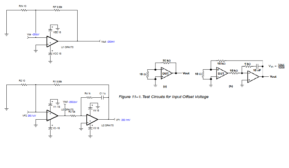
When referring 11-8 and 11-9 of "Chapter 11 Understanding Op Amp Parameters" (SLOA083), the correct method is to configure servo loop. Also, it mentions that "The action of the loop is to maintain the output of the DUT at zero volts.

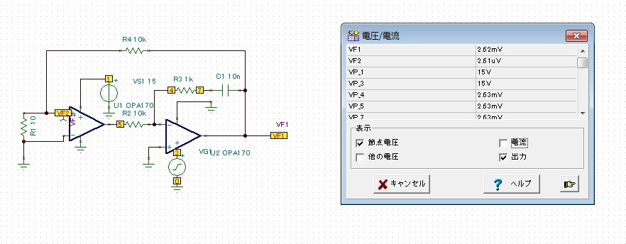
However, when simulation this by TINA-TI, there could not be found the output voltage of DUT was zero volts. (We used OPA170 model for this reference.)

Please refer to the test result on this as below; 


We would appreciate if you could show some detailed explanation on this measurement method.

We thank you in advance for your information.

Best regards,

  • I have never found a really good explanation of the servo loop for opamp characterization tests. I presume the servo amplifier is there to ensure the output of the DUT is unloaded because the reality of the circuit is really testing AVOL. An infinite AVOL would imply 0Vos, but what you have is VF1 divided by the noise gain of the circuit leaving you with Vos of the DUT.
    At nodes VP_4 and VP_5 across the 10kΩ resistor, the voltage measures the same 2.63mV so no current is coming out of the DUT. I would say that is unloaded.
    I say artifact of SPICE!

    -Ken
  • Atsushi,

    The problem with your circuit is that you incorrectly connected the feedback in the first op amp - it must be connected to the non-inverting input terminal (and not inverting) since the second op amp already provides the negative phase shift; '- ' and '- ' would makes it a positive feedback thus your output slams against its rail.

    Having said that, you do not need to split the hairs in the input offset measurement and to require use of servo-loop. The error involve in Vos reading due to Vout not equal zero is miniscule (see first configuration below) since the effect of Vout on Vos is very small: Vos_err=Vout/AOL. Thus with OPA141 DC open-loop gain of 120dB (1,000,000), the Vos error is 1uV per 1V at the output - see below: Vout=(1+9.99k/10)*Vos=1000*Vos and Vos_error = Vout/1E6 = 250mV/1E6=0.25uV


  • Ken,

    The reason for use of the servo-loop in op amp characterization is to have a full control of the DUT's output voltage.  Since the input voltage offset, Vos, is typically specified with the input common-mode and output voltage in the middle between supplies, Vcm=Vout=Vs/2, any change in Vout from Vs/2 while measuring Vos will result in the error in Vos. 

    If you have a good multimeter, you could determine Vos just by placing DUT in a follower configuration and with the input grounded (with dual supply) measure the Vout=Vos.  However, if you need to significantly gain up the Vos in order to measure it precisely at the output, this will result in Vout being far removed from the specified mid-supply condition, which creates the open-loop error: Vos_err=Vout/AOL.  Therefore, placing the op amp in the servo-loop allows the DUT output to stay close to Vs/2 (thus avoiding AOL related Vos error) while measuring the DUT's gained up Vos at the output of the second op amp.

    Also, since the non-inverting input of the second op amp (thus DUT's output) can be easily controlled with a DAC, the use of the servo-loop allow precise control of the DUT output in other tests like AOL where swing to the rail must be well controlled.