This thread has been locked.

If you have a related question, please click the "Ask a related question" button in the top right corner. The newly created question will be automatically linked to this question.

AMC1100, Fixed Gain Error?

Other Parts Discussed in Thread: AMC1100, LM7705

Hi,

I use AMC1100 to measure high-AC voltage on 60Hz, all phases+neutral, as per attached schematics (please look below).To do preliminary tests, I used a waveform generator to apply 50mVpp/60Hz/sine between VinP and VinM. Then, I measured the output voltage of my AMC1100, between VoutP and VoutM: the voltage is 2.55V+200mVpp. Since I have 5V on VDD1 and 5V on VDD2, the DC value is as per datasheet. However, the gain is 4 only. Is there something wrong with my design?

The devices are marked as AMC11000-TI Z518-2AHG4. I have been told that G4 means Green-RoHs compliant, but I wonder if this could mean a special gain of 4 instead: my design is rather simple because the PCB must be as small as possible...

Thanks and Regards,

Etienne

AMC1100QuestionAboutGain.pdf

  • My issue is related to VoutM: it must not be connected to GND2. The output on VoutM is 2.55V-4*signal...
  • Hello Etienne,

    It seems to me that the AMC1100 is working properly. Each output has a single ended gain of 4 such that when the outputs are measured differentially the overall gain is 8.

    Also, as you stated in your last forum post: the AMC1100 output terminals MUST NOT be connected to ground! You need to correct this detail on your circuit.

    VoutN will have the same common mode signal as VoutP and will have a differential signal inverted from that of the other output.

    In order to fully utilize the gain of 8 from the AMC1100 you could use a differential amplifier in order to convert the AMC1100 output to a single ended voltage.

    Hope this helps.

    Best regards,

    Jose

  •  Hi Etienne,

    the amplifier has a full differential Output, so the Output Signal is between VoutP and VOutN and can swing +-. As you tie VOutN to Gnd you shorten the Output and you loose half of the Signal (half of the possible Output swing) so you see half of the gain ==> 4.

    If you want to get a single ended Output of your sensing module, you have to use a adder.

    I currently develop a similar Thing, my eval board will be available end of the week (I hope).

    If you Need linrar Output down to very low values, you have to use a small negative bias voltage. You can generate this voltage with a LM7705 to generate this voltage.

    With best regards

    Gerhard

  • Gerhard, I will implement a solution like yours (probably with my voltage reference of 1.5V on "R8G" instead of Agnd -to avoid the negative bias voltage-, if my next tests are positive).

    Thanks a lot to you and Jose!

    Etienne
  •  Hi Etienne,

    fine.

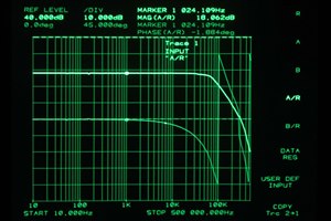
    In the meantime I tested my design, see Picture. The Transfer characteristic Looks nice and the gain is very Close to 8, so I think it will work fine in my Feedback Loop.

    With best regards

    Gerhard