This thread has been locked.

If you have a related question, please click the "Ask a related question" button in the top right corner. The newly created question will be automatically linked to this question.

INA125U not amplifying per the datasheet

Other Parts Discussed in Thread: INA125, INA122

Hi,

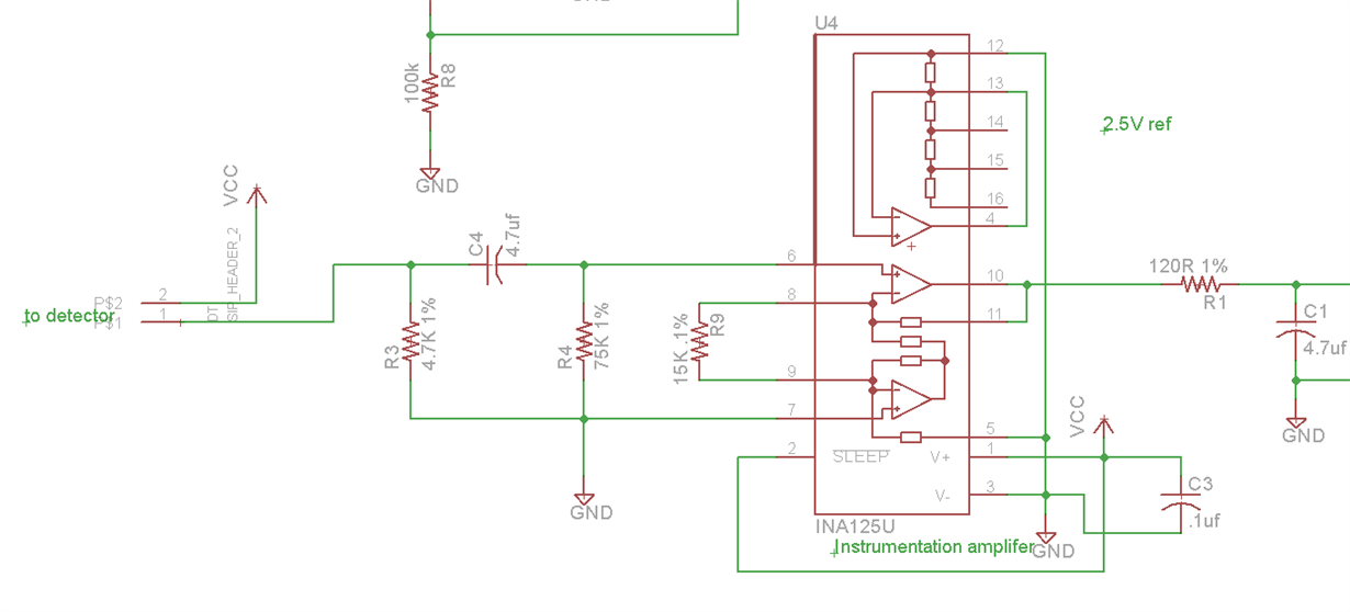
I have a INA125U connected to an light detector. The detector is reading a pulse from an LED emitter. I'm attempting to amplify the signal 18.3X using a 4.2Kohm resisitor for Rg. Schematic is attached, Rg is labeled incorrectly as a 15K so please ignore that. I have tried several different gain resistors and I don't get much if any change in the Output. I have also tried 3 different Amplifiers, all hand soldered. I have verified the Rg traces connect to the INA125, but it behaves as if they don't.

I have a very similar circuit using a INA122u that is working properly. The only difference is the sleep pin and the link for the Precision reference.  I need to get the INA125U to the same approximate level of amplification, the INA122 is using a 15K Rg. I would use the INA122 but I don't have any boards to mount it on yet.

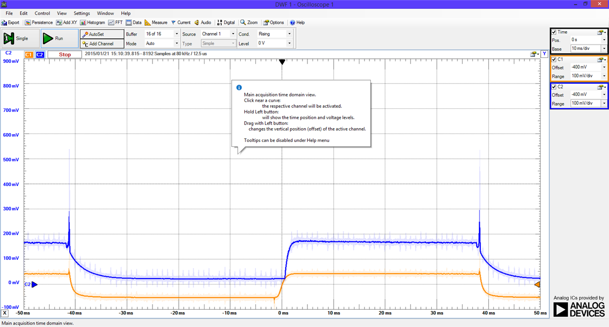
Scope trace of the INA125 gain is 64 (Rg = 1K) Orange is +Input, Blue is Output. Output is 100mv/div:

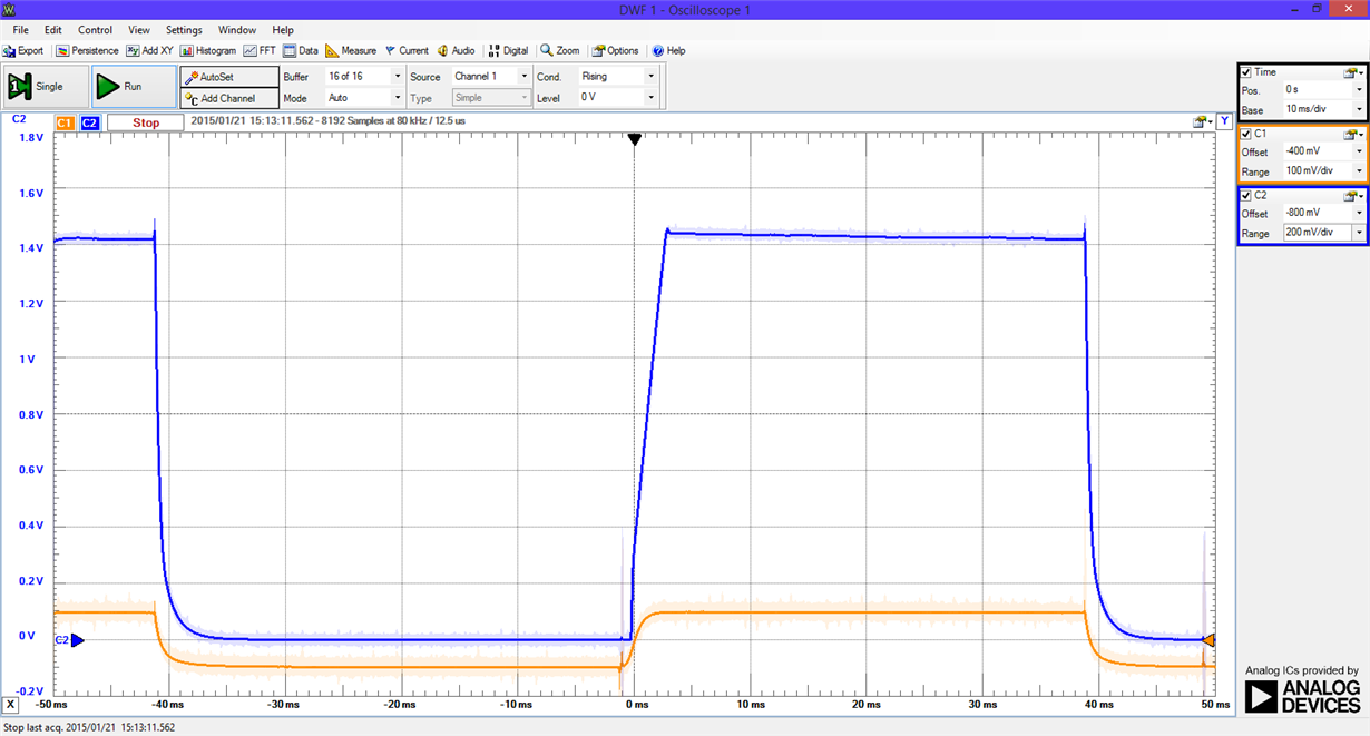
Scope trace of the INA122U at a gain of 18.3 (Rg = 15K) Orange is +Input, Blue is Output. Output is 200mv/div:

What am I doing wrong?

  • The INA125 input common mode voltage range does not extend all the way to the negative supply voltage, which in your case is ground:

    The input voltage will need to be above ~0.7V for the amplifier to start functioning in its linear region and providing the expected amplification. If you look in the INA122 datasheet you will notice that the input common mode range on that part extends to the negative supply. 

  • Hi John,

    I did not notice that difference, thanks for pointing it out. I will whip up a board with the INA122.

    Thanks!

    Todd
  • Hi, 

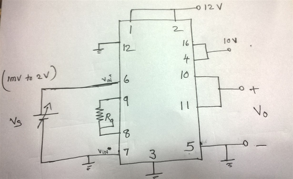
    I have connected INA125 as per the given schematic.Actually I have to connect a load cell across pin 6 and 7.For testing purpose ,I have given a voltage in the mV range to the pin6(Vin+) from a voltage source and grounded the pin7(Vin-). But the output voltage (at pin 10) is not getting changed. What will be the reason?Only for input voltages above 40mV, the output voltage is getting changed. When input not given, output voltage =11.186V.

    Some of the readings are as provided:

    For Rg= 62 k ohm,

    input =0.1V, output voltage =0.32V

    input =0.5V, output voltage =2.0V

    input =1V, output voltage =4.15V

    input =1.2V, output voltage =5V

  • Looks like you fell into the same trap I did. Your input voltage in reference to the negative supply is not high enough. According to John Caldwell in a post above it needs to be about 0.7 V above the negative supply or in your case ground.