This thread has been locked.

If you have a related question, please click the "Ask a related question" button in the top right corner. The newly created question will be automatically linked to this question.

Using PGA309EVM-USB to calibrate external sensor hardware

Other Parts Discussed in Thread: PGA309, PGA309EVM-USB

Hi

I have the PGA309EVM-USB and USB-DAQ hardware. I'd like to use the DAQ to calibrate my own sensor hardware which uses the PGA309.

I noticed that the DAQ controls the TEST input to the PGA309 on the EVM board, which is pulled up on the DAQ board.

Reading the PGA309 documentation it says that the TEST pin should be grounded for normal operation, but pulled high to allow an external uC to write to the registers. Does this mean if I want to let the DAQ program my PGA309, I need to connect the DAQ to my PGA309's TEST pin or can the PGA309 be calibrated with the TEST pin grounded?

Regards

Bob 

  • Hello Bob,

    The TEST pin on the PGA309 functions as follows:

    • When TEST is low, the PGA309 is in normal mode. In this mode, the PGA309 automatically reads from the data saved to the external EEPROM at a regular interval and updates its register values. The only way to change the settings of the PGA309 in this mode is to write to the EEPROM.
    • When TEST is high, the PGA309 is in test mode. This means that the auto-read and auto-update of the PGA309 registers from the EEPROM is suspended. In this mode you can write directly to the PGA309 registers and the changes will "stick," as long as test mode is maintained.

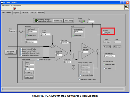
    The TEST pin on the PGA309EVM-USB is controlled by a GPIO pin on the USB-DAQ board. By default, TEST is low, and the calibration procedure writes directly to the EEPROM. However, you can click a check box on the Block Diagram tab (as shown below) to enable TEST mode.

    If you want to calibrate your PGA309 module using the USB-DAQ, I recommend connecting the TEST pin on your PGA309 to the DAQ net which controls TEST on the EVM. For maximum functionality, you can also place resistor footprints which either pull the pin up or down if you need to do more testing later.

    Best regards,

    Ian Williams
    Linear Applications Engineer
    Precision Analog - Op Amps

  • Hi Ian

    With the click box not selected, so TEST is low, are you saying that the DAQ uses the I2C bus to write directly into the EEPROM, and does not use ONE_WIRE?

    I want to program my hardware using the DAQ to drive the PRG pin in Vout, 4-wire mode. When my hardware is in the oven, I plan to power it from a local battery, so I was going to use a 3-pin header to connect PRG, Vout and GND of the PGA309 to the DAQ using J3-11, J3-5 and J3-6 respectively. If I use a resistor on my hardware to pull up the test pin during calibration, can I use Auto-Cal to perform the calibration? After calibration, I'll fit a pull down on TEST.

    As an aside, I have a few comments regarding the supplied EVM documentation (SBOU084A). Section 2.4 PGA_Test_Board: Signal Definitions and Pinouts list the pinout of the J1 and J2 connectors, listing which signals are used on this EVM. The list is wrong. For example, J1-1 DAC_A is shown as not used on this EVM, but if you look at the schematics, this pin is driven by a DAC on the DAQ to control the sensor emulator diode input. J1-5 ADS1+ and J1-6 ADS1- are also shown as not used. Obviously this is incorrect. I have traced the pinout myself using the schematics, but I think the document should be updated to have the correct information.

    Of more concern, 4.13 Create Pre-Cal File: Detailed Description has a table which describes the various Pre-Cal File fields. Step 7 says that the Configure Temperature is "described in detail in section xx of this document". It looks like this section hasn't been written yet. Are there any plans to write this section? Maybe there is an errata document that I haven't seen yet?

    One final thing, the silkscreen on the EVM is incorrect. The pin header labelled SDA1 actually goes to the EEPROM I2C clock and the pin labelled SCL1 goes to the data pin.

    I don't mean to go on, but I tend to use TI as much as I can, mainly due to the quality of the documentation, so I'm a little surprised.

    Regards

    Bob

  • Hello Bob,

    In the EVM's normal operation, the USB-DAQ uses a one-wire-initiated two-wire EEPROM transaction to write to the EEPROM. The transaction is triggered and data is sent to the PGA309 over the one-wire interface, then the PGA309 passes the communication over the I2C interface to the EEPROM. This process is detailed in the PGA309 User's Guide, section 4.7.

    If you want to program your hardware using the DAQ, you should connect your PCB as described in your reply. However, the TEST pin remains low during calibration, since the calibration uses the one-wire-initiated two-wire EEPROM transactions to write directly to the EEPROM. Therefore, do not use a pull-up resistor during the calibration program, but a pull-down.

    I apologize for the documentation errors and will investigate them.

    Best regards,

    Ian Williams