This thread has been locked.

If you have a related question, please click the "Ask a related question" button in the top right corner. The newly created question will be automatically linked to this question.

INA826 circuit not working as expected

Other Parts Discussed in Thread: INA826, TINA-TI

Hi. I'm trying to implement a PT100 amplifying circuit with INA826 as the one proposed here (three-wire circuit, figure 6). I've made the following modifications: single-voltage supply (3.3V) and a 1.65V offset, so that the output is between 0 and 3.3). However, when I simulate the circuit in TINA it gives me completely differrent, non-linear outputs, as compared to the calculating spreadsheet provided.

Could you please advice on why I'm not having the desired results?

Thanks!

  • Hello Martin,
    Can you please share the TINA-TI simulation file that has your modifications?
  • Thanks for your quick reply Pete. The computer I made the simulation on got corrupted last night after a failed MAcOSX upgrade. I will try and get the files when I get home. But in the meantime, below is the schematic.

    On the spreadsheet, I set the following parameters:

    -Low scale temp: -10C

    -High scale temp: 40C

    -Low scale Vout: -1.65V

    -High Scale Vout: 1.65V

    -Vref: 3.3V

    -R1: 2200 ohm

  • I was finally able to get my mac up and running. Here is the simulation file. Please let me know if you find whats wrong with it.

    Thanks!birra_data_cap.TSC

  • Hello Martin,

    Thanks for the additional information and sorry for the delay...I have been out of the office.  I will review the article, spreadsheet, and TINA-TI simulation and get back with you early next week.  

  • Hello Martin,

    Sorry for the delay.

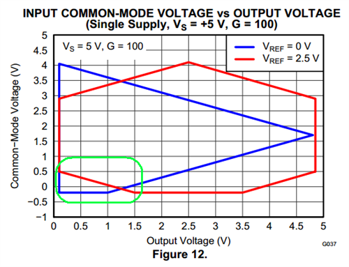
    The issue with the INA826 circuit revolves around the input common-mode vs. output swing range. Please refer to Figures 9-16 of the INA826 data sheet. Your situation is closest to Figure 12, shown below. Even though there is a mid-supply reference voltage, the output will not be linear due to the the green circled area as shown below.


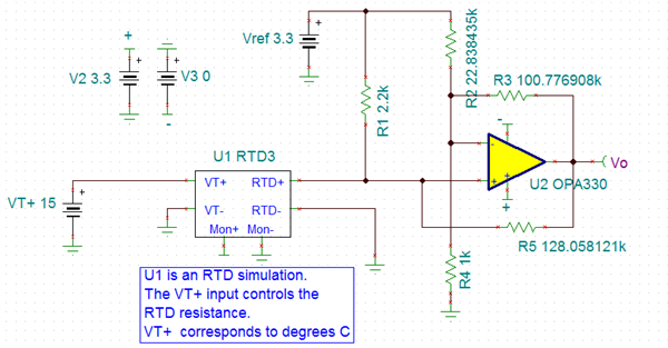
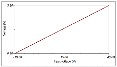
    The most straightforward approach to solving the issue (which is the desire for a single supply solution, if I understand correctly) is to replace the instrumentation amplifier solution with a rail-to-rail input/output op amp topology. I have provided the calculation spreadsheet and TINA-TI simulation below.  Note that I set the output swing from 100mV to 3.2V so as not to saturate the output of the op amp.  I hope this helps.

    RTD_Linearization_v7_ps.xls

    RTD_Linearization_Op_Amp_Circuit_ps.TSC

    Here is the circuit.  Note that I used the exact resistor values from the spreadsheet.  You will need to find the closest standard resistor values for the actual implementation.

    Here are the results:

    *Note:  The x-axis is actually temperature.*