This thread has been locked.

If you have a related question, please click the "Ask a related question" button in the top right corner. The newly created question will be automatically linked to this question.

ISO124 - powering down supply

Other Parts Discussed in Thread: ISO124, INA114, INA141, INA129, INA128

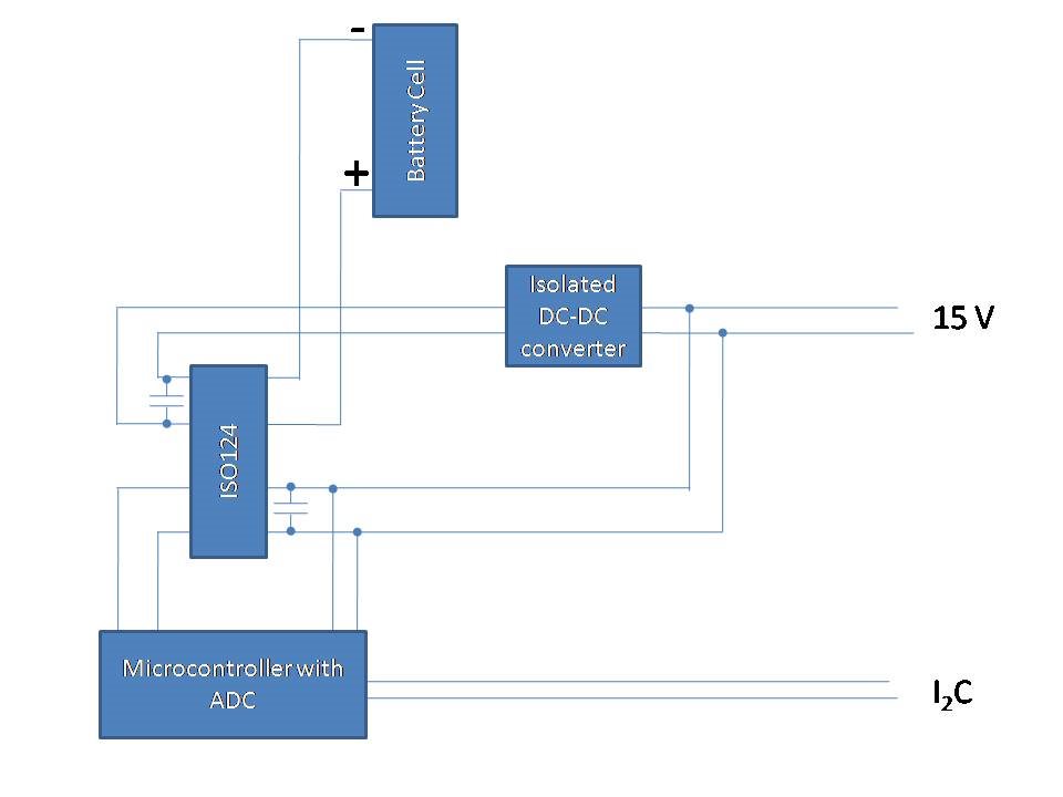
I am planning to use multiple ISO124 devices i(one per cell) in a battery voltage monitor. I want to reduce Vin current to the absolute minimum (nano-amp range preferably) to avoid distorting test data, so will be powering Vs1 and Vs2 from external power. A microcontroller will read and process Vout data.

I have three questions

a) Does this sound practicable as an approach?

b) If so, will it damage the ISO124 if Vin is left connected when the power supplies are powered down?

c)If Vin is connected with the the power supply off, will there be any current at Vin?

  • Hello John Hardy,

    a)      The ISO124 can definitely provide you with isolation in the type of application you have described. The requirement of nano-amp input bias current is, however, outside of the capabilities of the part. You will need to include an instrumentation amplifier with smaller input bias current specifications (e.g. INA128, INA129, INA114, and INA141.)

    b)      I would strongly discourage you from allowing voltages on the ISO124 inputs when the supplies are down. Yes, the device could be damaged under these conditions.

    c)       Yes; if there is an input signal present, then there will be current flowing into the input of the ISO124 even if the supplies are off.

    Hope this helps.

    Best regards,

    Jose

  • That is most helpful Jose - many thanks

  • Hi Jose you said:

    "I would strongly discourage you from allowing voltages on the ISO124 inputs when the supplies are down..."

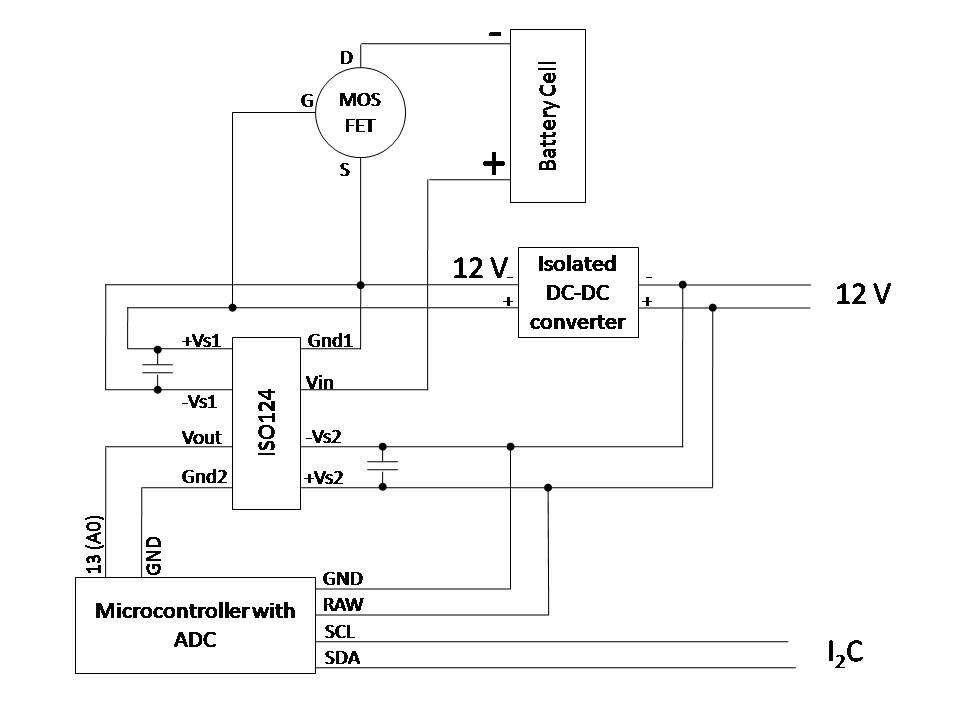
    Would it be sensible to use a MOSFET to isolate the battery cell negative in this fashion, or would the small source-to-drain leakage of the MOSFET still be enough to damage the ISO124?

  • Hello John Hardy,

    I think the MOSFET approach is sensible. My only comment is the polarity of the connection to the battery. You are showing a MOSFET enabled by a positive gate to source voltage; therefore I think the connection might work better if the positive terminal of the battery were connected to the drain of the MOSFET and the source of the MOSFET were connected to the Vin terminal.

    Best regards,

    Jose

  • Jose: many thanks for the speedy reply - most helpful


    John

  • Apologies - I am still having trouble with this. Any further suggestions would be much appreciated.

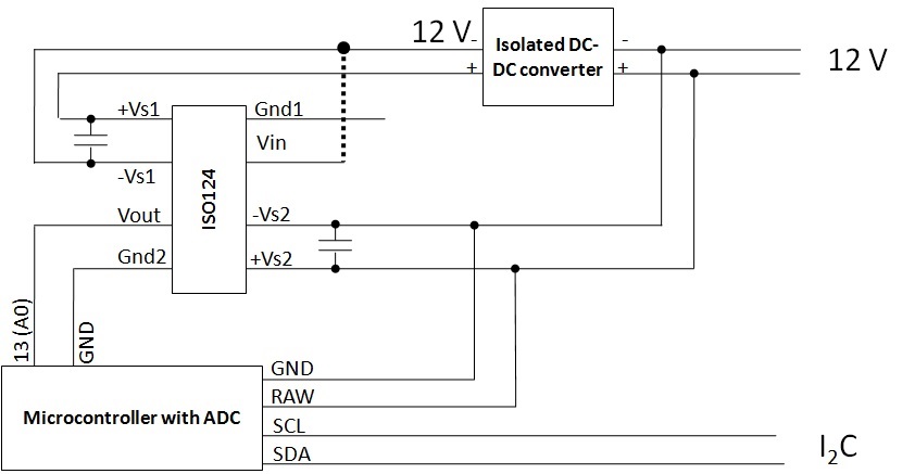
    Essentially If either Vin or Gnd1 are connected to Vs1 or Vs2, the output voltage is spurious. So this circuit works fine (the voltage between Gnd1 and Vin is replicated at Gnd2/Vout) until I make the connection shown as dotted below:

    This makes it impossible to implement my earlier circuit. Any suggestions?

  • Hello John Hardy,

    Please remember that you need to bias the GND1 and GND2 terminals of the ISO124. Your schematic above has no provision for that.

    Figure 21 of the ISO124 datasheet shows an approach to that using a zener diode. My recommendation would be try that not only for GND1 but also for GND2.

    Hope this helps.

    Best regards,

    Jose

  • Many thanks Jose