This thread has been locked.

If you have a related question, please click the "Ask a related question" button in the top right corner. The newly created question will be automatically linked to this question.

Problem using LMP7721 Evaluation board in Transimpedance configuration.

Other Parts Discussed in Thread: LMP7721

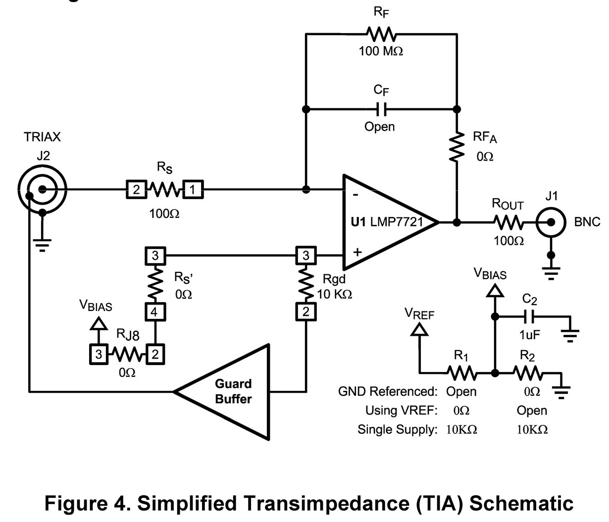
I have two LMP7721 evaluation boards which I have modified to the Transimpedance configuration as shown in the figure 4 of the  "LMP7721 Multi-Function Evaluation Board Users' Guide" [http://www.ti.com/lit/ug/snou004/snou004.pdf]. This is to be used with a photodiodes in photovoltaic mode.

The only difference is that I use either a 10 M or a 1M feedback resistors instead of 100M. I use +/- 2.5 volt power supplies and the positive input is grounded (Vbias = 0).  My problem is that both boards have a fixed output of -1.36 volts regardless of input current or gain!

I have grounded the input without any change to the output. I also cleaned the board according to the video posted on the TI web page. 

With 1 M Ohm feedback resistor when the input is grounded (i.e., VIN- ~ 0.000)  VIN+ = 0.000 the output reads -1.359 and Vguard = -1.915 Volts. 

I have also connected a photodiode with output current of 0.43 nA and tried both polarities. The output remains constant.

I have the modifications checked by another engineer to make sure that the TIA configuration is that of figure 4.


Am I missing something? Has anyone else encountered this problem?


Vahe G.


  • Hi Vahe,

    You cannot ground the input (center terminal of the triax). That is an "illegal" condition since you short out the feedback path and ground both of the amplifiers inputs. Grounding both of the 7721's inputs will cause it to rail.

    For "zero" output, the input should be left floating (unconnected).

    The guard buffer output should be within millivolts of ground. It sounds like your "reference" is not grounded.

    Have you checked with an oscilloscope that you are not getting an oscillation?

    Try this:

    Make sure the positive input (and buffer driver input) are grounded. Measure the resistance (with power off) from the 7721 "+" pin to ground. It should be 10K in the circuit shown above. My guess is you have something missconfigured with R1, R2 or Rs' or RJ8.

    With a 1M feedback, make sure the input is FLOATING (not grounded or connected) with nothing other than the feedback resistor connected.

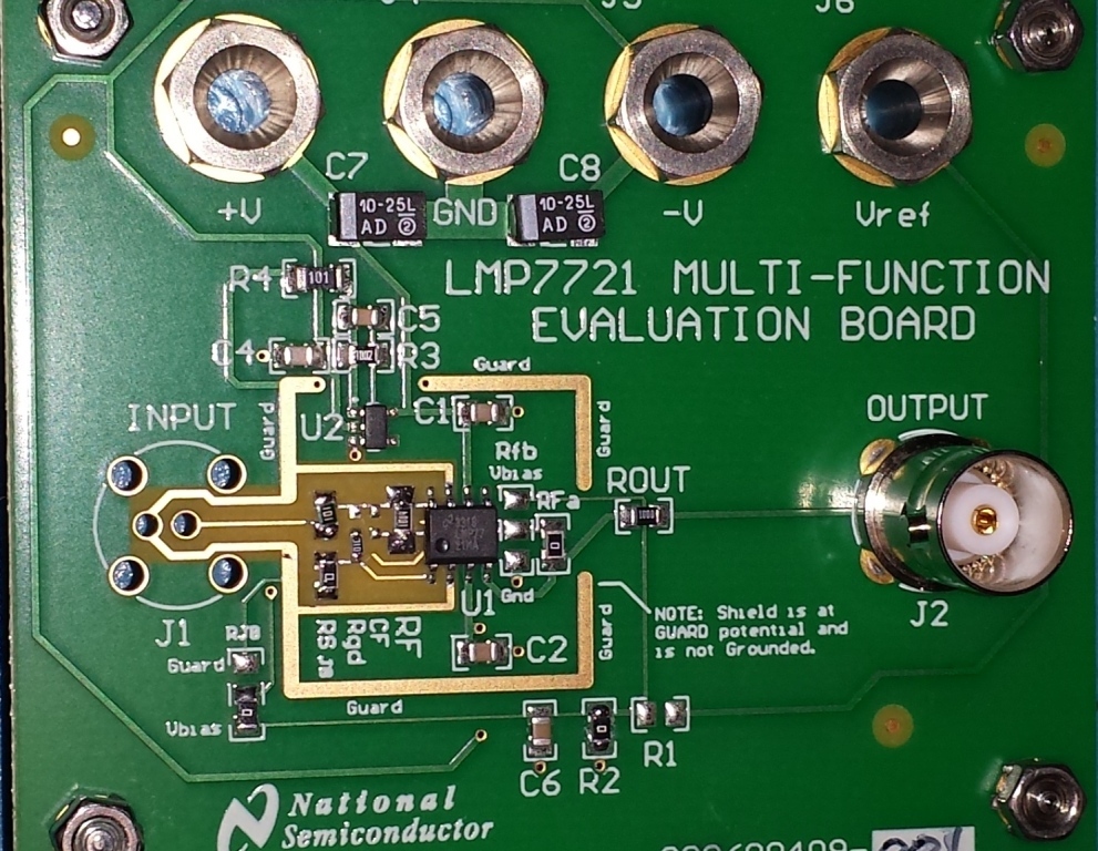
    If you can, take a close-up picture of the board and attach it (click "Use Rich Formatting" in the lower right to enable the editing tools and use the "media" icon to attach a picture).

    Regards,
  • Hello Paul, thank you for your prompt response. Yes I understand that you can not ground the negative input in the transimpedance mode [you had mentioned in one of your earlier posts]. I did that just to induce a change in the output.

    Per your suggestion I checked the output with an oscilloscope. There is no oscillation. The output as I indicated previously is at -1.359 volts DC.

    I rechecked the resistance between ground and the pin 1 of 7721 (Vin+) it is zero.

    The resistance between ground and pin 3 of 7715  is 10 K.

    It is interesting that when power is on the potential difference between pin 1 of 7721 and ground is zero while the potential difference between pin 3 of 7715 (which is connected to pin 1 of 7721 via a 10 k resistor) is -1.73 volts!

    I will try your other suggestions later today.

    I have attached a close-up photograph of the board as it is currently configured.   

    Regards,

    Vahe

  • Hello Vahe,

    Hmm... It looks good. Nice picture! Very Helpful! Worth several kilowords! Looks very clean.

    What happens if you short the feedback resistor (turning it into a follower)? The output should go to zero (or whatever 7721 pin 1 potential is). If the output goes to zero, then there is a leakage on the input side of the feedback resistor or input path. Look under the SOIC and the resistor for burned flux. I find it easier to mount the resistor vertically on it's edge (easier to grab with the tweezers) when bread boarding and much easier to clean.

    What is the voltage across Rgd? It sounds like something is wrong with the buffer input and it is drawing high current. Does the voltage on the input of the guard buffer match the buffer output voltage (is it "buffering").

    Is the output voltage "solid", or does it move as you touch or probe various points (J1 input , touching RF, etc). Have you verified that all the components are the values you expect? Are the 0 ohms truly zero? They are easy to break/damage/delaminate.

    Are the supply currents symmetrical? Is anything getting hot?

    Did you also clean the bottom of the board - particularity around the center input pin?

    I will be traveling on business the next few days - so my responses may be delayed.

    Regards,