This thread has been locked.

If you have a related question, please click the "Ask a related question" button in the top right corner. The newly created question will be automatically linked to this question.

INA149 grounding

Other Parts Discussed in Thread: INA149, DRV411

Hi there,

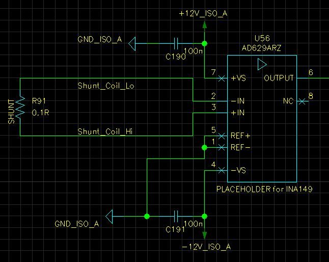
look at my design. (Note I use INA149, but have schematics with AD629 as a placeholder; don't be confused :-)

What's my concern?

Does INA149 works correctly with inputs floating as you see in my schematics? I've got high-side shunt for current measurement, expect > 200 V common voltage.

There is dirrect connection of shunt terminals to INA149 inputs.

Please, confirm that I don't need to ground  -IN or +IN input. My analogue ground is a middle of +/-12V TRACO ouput.

Thanks

Petr

  • Hello Petr,

    It appears as thought the current you're trying to measure actually flows through the inputs of the INA149, which will cause voltage drops across the internal resistors of the device (which are trimmed ratiometrically...not to an absolute value). So, I can't recommend using the device in this manner. One option is to modify your design such that the measured current does not flow through the device itself. Alternately, perhaps you'd be interested in the DRV411.

    I hope this helps.
  • Pete,

    thanks for prompt reply.
    Actually, I've put the shunt to the schematics for iluustration. In fact the shunt is part of power stage circuit (buck/boost converter) - for high-side current measurement. So the current flows thru shunt to the load and two voltage potentials at sshunt terminals go to INA149 (with common mode voltage). Dataassheet - fig. 46 - I have it simular, except for compensation resistor as my shunt is 0.1 ohm only.
    Does it make sense now?
  • Hello Petr,
    Yes, now it makes sense. Given +/-12V supplies, the INA149's common-mode range is ~+/-210V (please see Figure 3 in the data sheet).
  • OK, so can you confirm INA149 will operate well even if there is no connection to ground (middle of symetric dual supply voltage) at IN+ or IN-? 

  • Hello Petr,

    Figure 46, as you referenced, does not have either IN+ or IN- (pins 3 and 2) connected to ground. IN+ and IN- are connected across the shunt resistor, Rs.