This thread has been locked.

If you have a related question, please click the "Ask a related question" button in the top right corner. The newly created question will be automatically linked to this question.

Problem with INA826 and OPA333

Other Parts Discussed in Thread: OPA333, INA826, TINA-TI, INA326

Hi all,

We intend to use INA826 and OPA333 for our design.

Goal: Convert input voltage from sensor (0V - 5V) to voltage for ADC (0V - 3.3V).

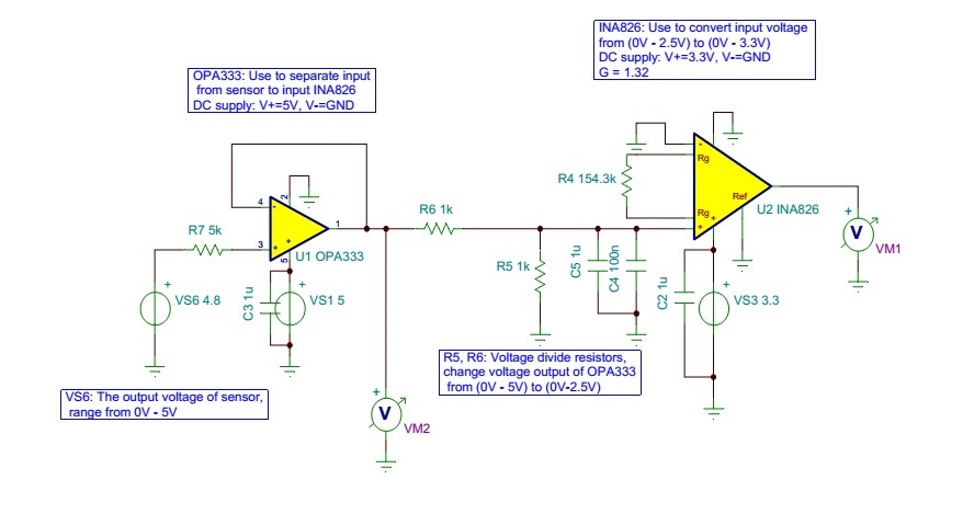
I use the TINA-TI tool to simulate the circuit:

The .TSC file: 2425.opa333_ina826.TSC

1.Question with OPA333:

We get the input voltage for OPA333 is from 0V - 5V (from temperature sensors), with voltage divine resistors (2 resistors with value 1 kOhm) connected directly to output of OPA333, the output of OPA333 is just linear with input voltage from 0 - ~4.75V, with the input range >4.75V, the output of OPA333 is saturated at 4.75V (can not reach 5V as we expected)

Question1: How can we get the output of OPA333 is full (0V-5V)?

2. Question with INA826:

With the single supply +3.3VDC, the output of INA826 is just linear with input voltage from 0 - ~2.1V, according to formula Vout = G*(Vin+ - Vin-) and G=1.32. When input voltage from >2.1V to 2.5V, the output of INA826 is saturated at 2.76V (can not reach 3.3V as we desired).

Question2: How can we convert the input voltage for INA826 from (0V - 2.5V) to full (0V - 3.3V)?

Please help review and give us any better solution.

Thanks and Best Regards,

Hoang Manh

  • Hello Hoang,

    Please see attached simulation.  I used the INA326, which is a RRI/O instrumentation amplifier with a current-mirror topology.  It provides a high-impedance input and can attenuate the input signal based on 2 external resistor values.  I added a 100mV reference voltage to pedestal the output so that the output stage is operating in a linear region.  Therefore your input of 0-5V translates to 0.1V-3.3V.

    hoang.TSC

  • Hello Pete,

    Thank you very much for your quick reply.

    I think your solution is simpler, I just want to ask:

    1. Can you explain a little why we have to add 100mV reference voltage?
    2. If we don't add this reference voltage, and change the value of R2 to 132k, do the circuit work correctly?

    Thank you again for your solution.

    Best Regards,

    Hoang
  • Hello Hoang,

    For the INA326, the output voltage swing to the rail is 75mV as shown below:

    If you try to output anything closer to the rails, the output will be non-linear.

    For a much more detailed description, please 

  • Hello Hoang,

    Sorry...had a technical problem.

    Anyways, there is an excellent series of online videos (called TI Precision Labs...link in the previous post) that has a video that discusses the input and output limitations of amplifiers. This video will give you a much more detailed answer to your question.

    So, by adding the 100mV reference voltage, an input of '0' equates to an output of 100mV, which is in the linear operating region of the output of the device. Similarly, setting the gain such that an input of '5' equates to an output of 3.2V (which is 100mV from the positive supply voltage of 3.3V) ensures the output is operating linearly.
  • Hello Pete,

    Thank you for your reply. Those videos are really awesome, I've learnt alot from them :).

    We finish the schematic:

    About the 100mV reference voltage, because the valid output of sensor is from 0.5V-4.5V, so in this version of our schematic, we decided to skip this reference voltage.

    Please take a look and feel free to give me any ideas.

    Many thanks and best regards,

    Hoang 

  • Hello Hoang,

    One more suggestion: with the INA326, make sure you place R26 close to pins 1 and 8 in order to minimize capacitance.
  • Hi Pete,

    I'll note your suggestion for layout team :).

    Thank you for your kindly support :)

    Hoang,