This thread has been locked.

If you have a related question, please click the "Ask a related question" button in the top right corner. The newly created question will be automatically linked to this question.

PGA 309 EVM support

Other Parts Discussed in Thread: PGA309EVM-USB, XTR115, PGA309

Just received a PGA309EVM-USB.

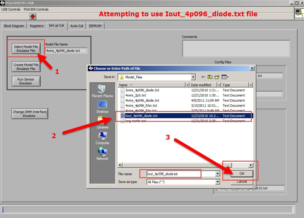
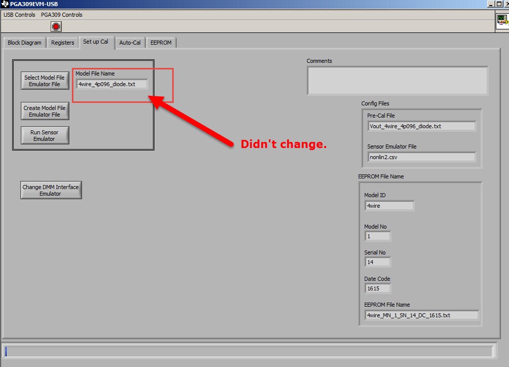
It will not load "Model File Emulator File" as claimed in the User Guide. It only keeps the default "4wire_4p096_diode.txt" even though there are many other selections when the pop up window opens.  WHY??????  I want to use "Iout_4p096_diode.txt" since I configured the jumpers for a 4 - 20.  Selecting that option is not changing the "Model File Name" field in the "Set up Cal" screen.  I had hoped to create a setup then save it for later recall.

Overall this is very poorly documented PERIOD in the user guide on how really to get started, and I can't seem to find any other instruction or resources beyond the less than helpful user guide.

I have configured the jumpers jp9, jp10, and jp11 for 4 - 20 operation.  everything else is default.  I just want to emulate the sensor, use internal temp sensor, and then play with this thing virtually before I apply to the real world.

And is there anywhere where there are any video or other help for this? Only a few questions on the forum for this and then not for the eval system software, only the hardware part itself the kit is designed for.

The selected file doesn’t "take" and the selection remains as the default selection, no matter which Model File is chosen !!!!

  • Hello Michael,

    I apologize for the difficulty in configuring the PGA309EVM-USB and the lack of easily accessible documentation.

    I believe that the problem you're having with the model file not "taking" is due to issues with User Account Control in Windows. If you are in Windows Vista, 7, or 8, you must run the program as an administrator in order to have full read/write access to the directories where the model and pre-cal files are saved. Simply right-click the PGA309EVM-USB executable, then click "Run as administrator."

    This presentation covers some basic set-up for 4W Vout and Iout modes which should help you get up and running quickly: Calibration = USB_DAQ + PGA309EVM.ppt

    Best regards,

    Ian Williams
    Linear Applications Engineer
    Precision Analog - Op Amps

  • Thank you that was very helpful so I bought a PGA 309 reference kit, I'll have questions on that unrelated to this, so I'll close this and post new questions separate.

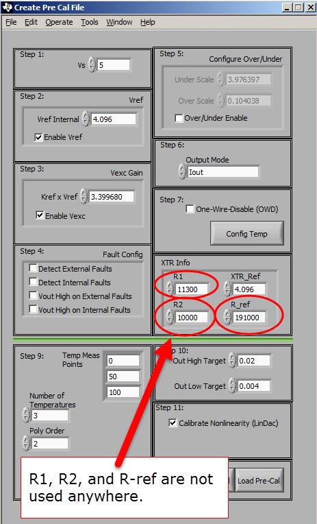
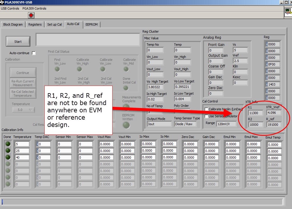
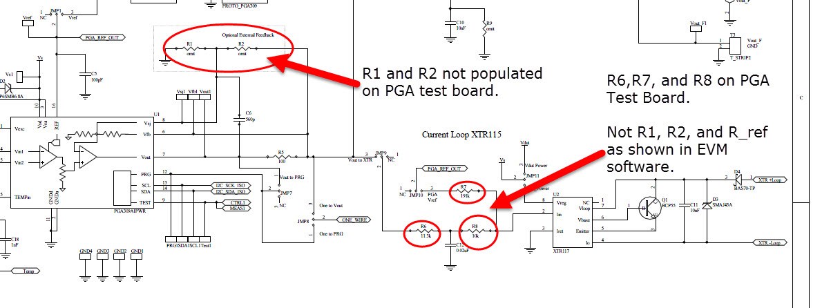
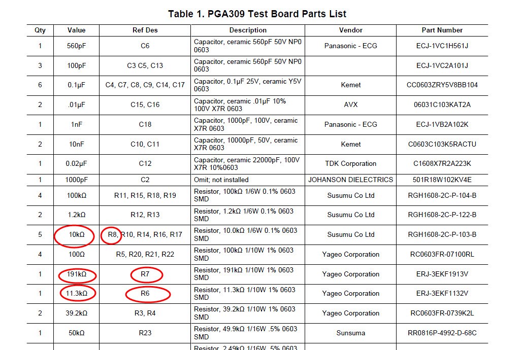
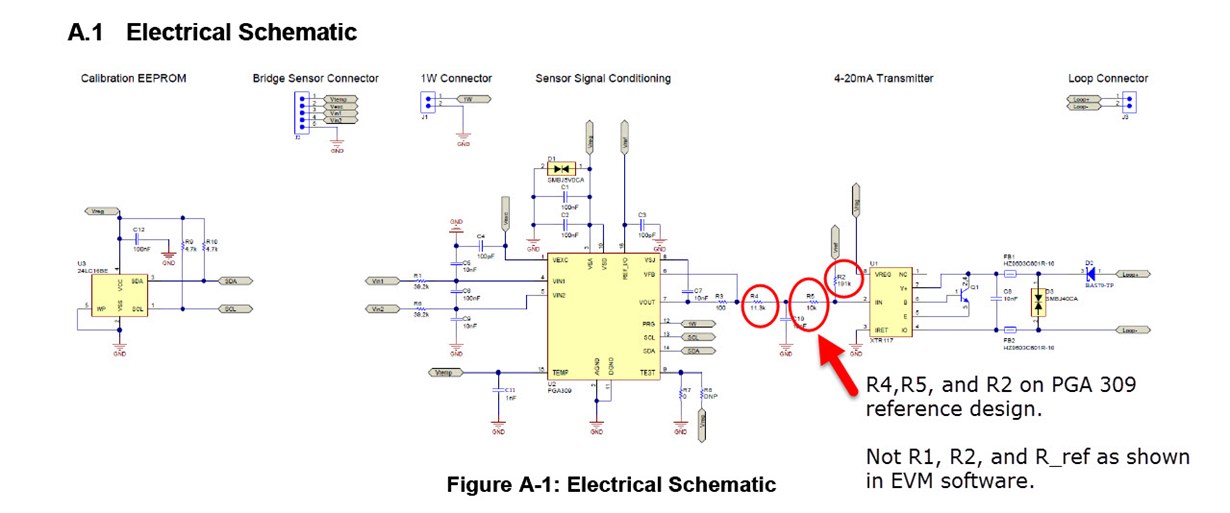
    I did find what I believe to be errata in a couple of software screens. I suspect those screens were OK at one time perhaps on an earlier revision of the PGA 309 EVM test board and the PGA 309 reference design. See my screen shots below. The resistors for the XTR115 circuit as called out in the software are R1, R2, and R_ref. With the values  of R1 as 11300 ohms, R2 as 10000 ohms and R_ref as 191000 ohms.

    Based on either the PGA 309 EVM test board and the PGA 309 reference design this is not possible for resistors R1, R2, and R_ref.  In the PGA 309 EVM schematic R1 and R2 are optional  and use for over/under alarms, and not populated on the PCBA.

    The only place these are called out as R1 and R2 and Rref (R3) are on page 1 of the document Using the XTR115 with the PGA309 to Generate 4mA to 20mA Output sboa107b.pdf


    Anyway, it might be confusing to some using the EVM test board and/or the reference design as the resistor references appear differently in the software screens.

    EVM Test Board schematic

    Reference Design Schematic