This thread has been locked.

If you have a related question, please click the "Ask a related question" button in the top right corner. The newly created question will be automatically linked to this question.

Interfacing PGA280 to piezo sensor

Other Parts Discussed in Thread: PGA280, TINA-TI

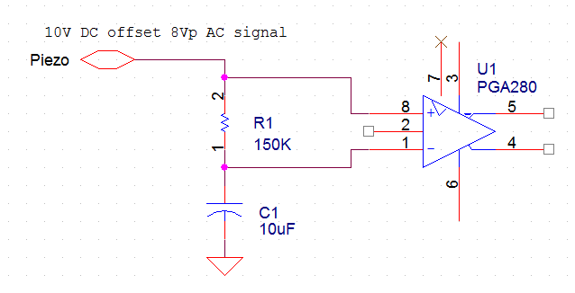
I'm planning to use PGA280 to amplify the signal from a piezo sensor before route it into the ADC. The ICP sensor has 8Vp AC signal with 10V DC offset. Since I need very low freq (down to 0.1 Hz) I must use electrolytic caps. So I'm wondering for a suitable input coupling scheme. Does anyone has suggestions?

I designed this one (see picture, please don't mind to the PGA280 pinout), simulated and tested and it seems to be good, but I've never seen something similar so I'm asking if it can have some drawback.

  • Hello Davide,

    This input scheme will work, but you need to be mindful of the PGA280's input voltage range. 

    The input voltage range of the PGA280 is from (VSN + 2.5V) to (VSP - 2.5V). The maximum power supply voltage across VSP and VSN is 36V, or more commonly, ±18V. However, the input voltage being applied from the piezoelectric sensor ranges from +2V to +18V. This means that you must provide at least (18V + 2.5V) = 20.5V to VSP. If not, you will see significant distortion due to the saturation of the PGA280 input stage. 

    I've attached a TINA-TI simulation schematic: PGA281 Piezo Interface.TSC

    Here's the result of the transient simulation with your 10V_dc + 8Vp_ac input signal, G=1/8 and symmetrical ±18V supplies. The distortion due to input stage saturation is clearly visible.


    Here's the same simulation, with the power supplies changed to an asymmetrical +22V and -14V scheme. The distortion is no longer present.


    Also keep in mind that the maximum small-signal bandwidth of the PGA280 across all gain settings is about 10 kHz. Refer to Figure 16 from the PGA280 data sheet below.


    Best regards,

    Ian Williams
    Linear Applications Engineer
    Precision Analog - Op Amps

  • Hello Ian, thank you for your quick and useful answer. I'm going to use your model to make some more simulation but I already spotted a problem in my design since I'm actually using 24V single supply and there is no "space at the bottom" for the input signal. I need to find a solution for this.

    Best regards