This thread has been locked.

If you have a related question, please click the "Ask a related question" button in the top right corner. The newly created question will be automatically linked to this question.

PGA309 with 350 ohm Load Cell

Other Parts Discussed in Thread: PGA309, XTR106

G'day

I am using the PGA309 design with 1k load cells without any problems.

My new design is to use 350 ohm load cells with Vref = 2.5 & Vexc = 2.075.  This creates more than 5.9mA consumption on the bridge alone.

Based on the reference design (SLAU526), which is the best way to reduce this current for a 4-20mA output?

Thanks

Cheers

Dirk

  • Hello Dirk,

    This is a tricky situation. Drawing such heavy current from Vexc will limit the range of voltage that can be sourced, and of course if you are using a current-output design, your total current draw can't exceed 3.5mA or so (to allow for some underscale output and headroom).

    It is possible to give yourself a bigger current budget using a buck (step-down) converter. The idea is that the converter steps the high-voltage, low-current loop supply to a low-voltage, higher-current supply for the two-wire circuit. Since it converts this power relatively efficiently, you can consume more than 4mA in the local circuit while still drawing less than 4mA overall from the loop. I'll check with a colleague to see if we have some documentation on this method.

    However, this doesn't change the fact that by Ohm's Law, if you use low-value resistors in your bridge you will draw high current from your excitation source. At this time, I don't see a way around that if you must use 350-ohm load cells.

    Best regards,

    Ian Williams
    Linear Applications Engineer
    Precision Analog - Op Amps

  • Thanks, much appreciated.

  • Hello again Dirk,

    The blog post below by my colleague Collin Wells describes this technique. Please be aware of some of the caveats associated with this implementation.

    In addition, LT provides a device called the LTC3255 which is designed exactly for this kind of application and can provide up to 7.4mA from a 4mA input. 

    Best regards,

    Ian Williams

  • Cheers. It looks interesting - I'll give a play.
  • Hi Dirk,

    One more comment: See pt. 3 of Collin's blog series for a technique where you can insert series resistance on the top and bottom side of the bridge to reduce current consumption below 4mA.

    This is also shown in Figure 5 of the XTR106 data sheet.

    Best regards,

    Ian Williams

  • Yes, this is the first thing I thought about. However, due to my design I needed the bridge to have a voltage of 2.075v to fit in with the existing 4-20mA RC network and eeprom parameters, as this is working well. But it looks like I have to anyway do another calc on the Vout / Iout depending on what I can sort out with the the bridge. So it will be a new design.

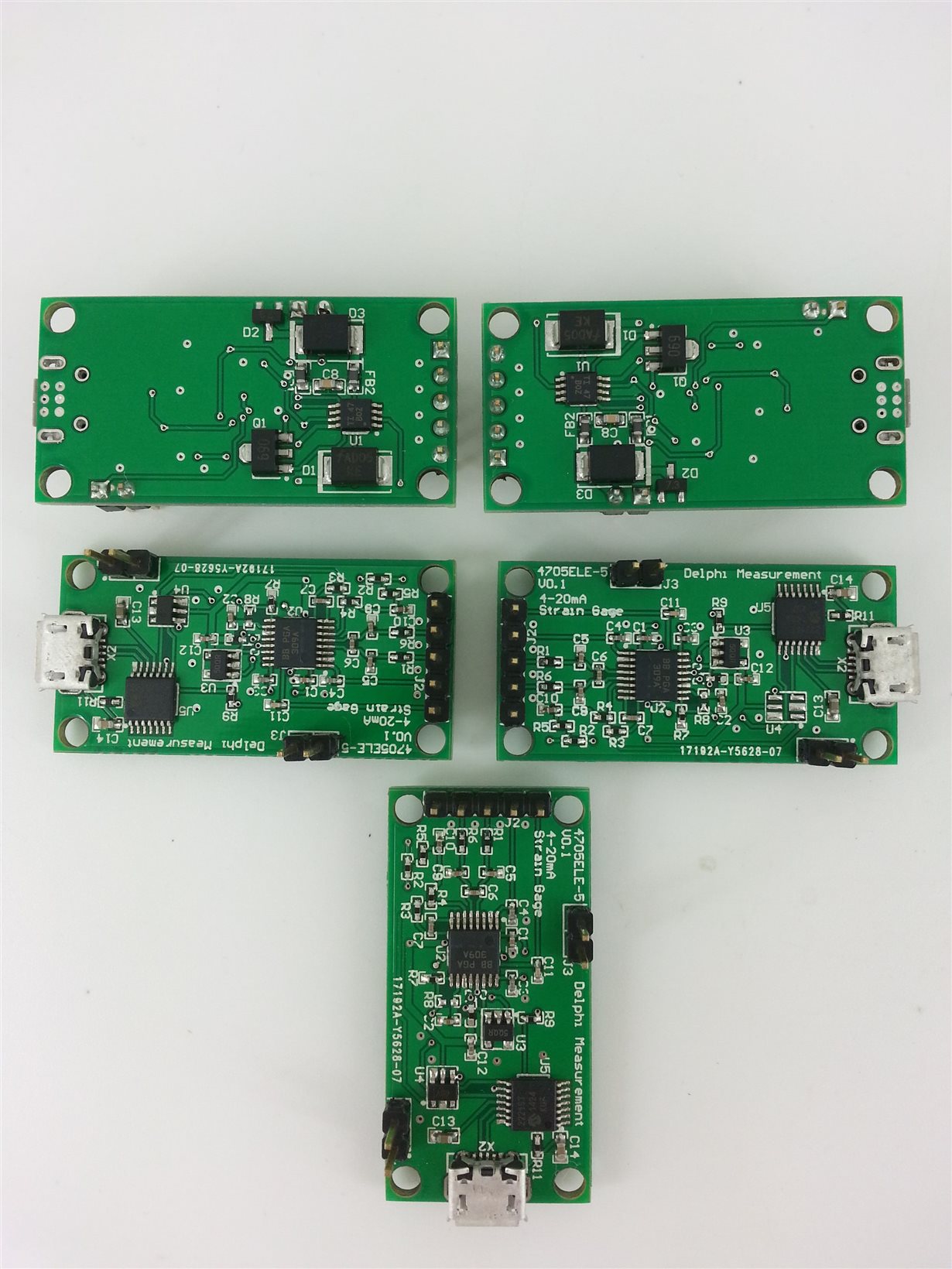
    Btw. I have to really thank you (and Iven Xu) for your design documentation. My prototypes are perfect (including 2-wire USB Android app for calibration) - see attached.

    Cheers mate

    Dirk

  • Hi Dirk,

    Wow, that is a beautiful set of boards! I'm very happy that our TI Precision Design was useful to you and helped get your system up and running quickly. That's exactly their intended purpose! I'll pass this along to Iven as well so he can see your kind feedback.

    Best regards,

    Ian Williams