This thread has been locked.

If you have a related question, please click the "Ask a related question" button in the top right corner. The newly created question will be automatically linked to this question.

Help selecting op-amp for instrumentation amplifier with low phase shift DC-5Khz

Other Parts Discussed in Thread: INA128, INA826, OPA192, INA126

I'm doing AC current sensing with a Rogowski Coil.  These are great in almost every way except for their output sensitivity: about 460uV per Amp.  That's basically in the noise for lower primary currents so before I send this signal across my PCB to the ADC I need to amplify it.  My initial thought was to use a simple op amp.

Power supply is +12V.

Gain will be provisioned as 30x.

Fundamental frequency of interest is 60Hz, but I need flat bandwidth reaching up to ~4Khz to measure harmonics in the signal output from the transducer.

Slew rate should be at least 1V/uSec to cover the frequencies of interest (i.e. I don't want to be slew rate limited).

The "killer" requirement is (ideally) NO phase shift within the bandwidth DC-5Khz.  I thought it would be a simple matter of selecting an op amp with a sufficiently high GBW and I've found many in the 5Mhz+ region that have a flat phase response to a reasonable fraction of that frequency, but begin with a 90 degree phase shift at DC (or so the graph with open-loop gain and phase vs. frequency shows).  That's a non-starter.

So my question:

Can you recommend an op amp that has low (preferably <1 degree) phase shift between DC-5khz?

  • Hello Doug,

    The open-loop phase is different from the closed loop phase. You should not observe any close loop phase shift until you start to run out of bandwidth. An illustration of this is given in our TI Precision Labs lecture on Bandwidth. Please see www.ti.com/precision-labs . Therefore using a circuit with plenty of bandwidth should be sufficient.

    That said, I am a little concerned about the phrase "...selecting op-amp for instrumentation amplifier...". To me it sounds like you're interested in building your own IA. There are a number of drawbacks to this, including but not limited to gain error, offset error, PCB space, drift, etc. A couple instrumentation amplifiers that you may want to evaluate are the INA128/9 and INA826. Though they do not have 5MHz bandwidth as you requested, their bandwidths are still ~20 times or more than the desired frequency range assuming a gain of 30V/V. They also meet or exceed 1V/us slew rate.
  • Hello Doug,

    The OPA192 has the phase shift of less than 1 degree up to 7.13kHz with the specs given in your post.  Below is a schematic of the circuit as well as bode plot of magnitude and phase.  I would recommend if you haven't already downloading Tina TI spice where you could simulate different Op Amps responses if this solution doesn't meet all your requirements.

    Figure1. Schematic of OPA192 with Gain of 30V/V

    Figure2. Magnitude and Phase Response of OPA192 with Gain of 30V/V

    Figure3. Schematic of OPA192 with Gain of 30V/V and Cload of 1pF

    Figure4. Magnitude and Phase Response of OPA192 with Gain of 30V/V and Cload of 1pF

    Attached below is the link for the OPA192:

    http://www.ti.com/product/OPA192

    Best regards,

    Errol Leon

    Texas Instruments Incorporated

    Analog Application Rotation Engineer

  • Thanks for the reply.

    This is what I get for being a high speed digital guy in an analog world...despite some experience building discrete audio amplifiers.  :)

    I had read a hint that open vs. closed loop phase would in fact be different but I wasn't seeing that in the preliminary simulation I was doing with the models I could find.

    I used the term "instrumentation amplifier" in a general sense because I know what they're often used for (accurate amplification of small signals such as those from transducers) but in fact did not want to build an InAmp.  I am reasonably aware of what goes into building them, and I doubt I could duplicate the benefits with three discrete amps (even if they were on the same die).

    I'll take a look at the INA126/8/9.  Thanks for the tip.

  • Earlier this morning I was using Tina for some analysis with a few different models and getting phase responses that mimicked the datasheets...in other words, not what I wanted.

    I then tried to be slick and simulated a dual op amp, placing one inside of the feedback loop of the other producing gain, with the hope to cancel the phase shift across the frequency range of interest. The end result was definitely more promising (< 0.8 degrees of phase shift below 5khz) but that assumes perfect match between parts (more likely on die but not guaranteed) and is generally less than ideal because it involves more support components. As inexpensive as they are, I really want to keep this as simple as possible.

    It's enlightening to see your example and the results I expect, so I think the next step is to duplicate your results. I'll let you know what I find. Thanks for your thorough reply.
  • Errol,

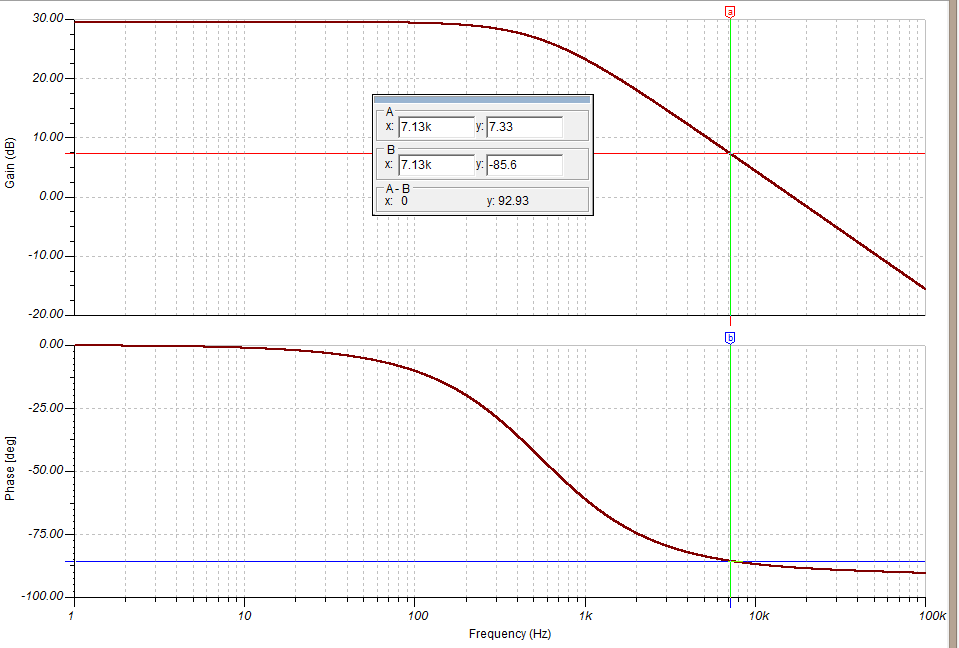
    I attempted to duplicate your efforts and while I did see ~29dB gain under 100Hz, the gain and phase dropped off far faster than in your graph.  Using the same 7.13khz frequency I was down to 7dB and -85 deg.  Which is consistent with what I've been seeing on a lot of my models (see attached).

    I'm not sure what's wrong.  I'm using a relatively recent version of Tina (not the latest, however), and I downloaded the OPA192 model from the product link provided.  When I imported the model it compiled ok and a quick check of the model text shows I have the correct model loaded.

  • Ha. Not a minute after posting my graph I realized one difference between your schematic and mine -- you configured a dual supply and I didn't, which chopped off the bottom half of the waveform. Of course I don't know why the phase / gain response of the amp would change in this case, but attaching a negative supply to the V- pin fixed the problem.

    Of course, I am limited to a single supply and this actually needs to be routed to the differential input of my ADC, so I'll need to either use a fully differential amp or figure out a mid-rail biasing scheme, but that's another topic. Thanks for the help.