This thread has been locked.

If you have a related question, please click the "Ask a related question" button in the top right corner. The newly created question will be automatically linked to this question.

ina114 help needed

Other Parts Discussed in Thread: INA114

I am working with ina114. I used two individual 9V batteries (unregulated) as power sources and Rg = 10Kohm. hence the gain should be 6. But when the differential voltage is 198mV, the output is -8.45V. However, if Rg (10KOhm)  is removed, then the output is 198mV.

I am unable to identify the problem here. Can anyone please help me.

  • Hi, I want to use INA114 amplifier for RTD measurement. While testing the response of IC, i was quite surprised to see that my output is not varying with input. I used two +9V batteries power up INA114 IC. Input of 0.38V is given from arduino board between the two input terminals. Output with ground as reference is 2.43V. The input changed to 42.4mV, yet the output is 2.43V. I an unable to figure out why the output remains same even if input is changing.

    INA114 pin connections:

    pin 1 ------> 10KOhm -----> pin 8

    pin 2 ------> arduino ground pin

    pin 3 ------> pin9 of arduino from where I am giving input

    pin 4 ------> -9V

    pin 5 ------> Ground

    pin 6 ------> Output

    pin 7 ------> +9V

    Can anybody please help me?

  • Hello sreeramya soratkal,

    Please ensure that you're measuring the voltage at the pins of the device using a digital multimeter (DMM).  You may want to also look at each pin (especially 3, 4, 5, 6, and 7) using an o-scope.  Also, since you're using the DIP package, I assume you're using a protoboard.  Such boards can sometimes have mechanical issues, so I recommend moving the circuit to another section of the protoboard.  

  • Hello sreeramya soratkal,

    It looks like you have created a separate thread for the same INA114 issue. Therefore I will join the two threads together.
  • Hi Pete Semig,

    Thanks for the immediate response. I rechecked the outputs at each pins using DMM. pin 3 gives the correct input. pin 4 shows -9.23V. pin 5 is at 0V. pin 6 is still stuck at 2.43V and pin 7 is at +9.25V . I changed the breadboard, yet did not find any luck.

    Is there some problem with the common mode signal?

    Regards,

    Ramya
  • Hello Ramya,

    Thank you for double checking the voltages and moving to a new location on the breadboard.

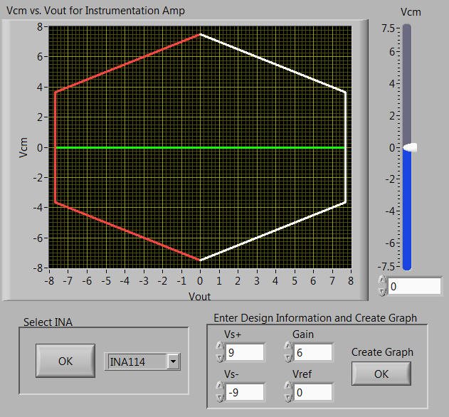
    There should be no issues with common-mode voltage since you're using a dual supply. You are well within the linear operating region as shown below. This tool can be downloaded from www.ti.com/.../ina-cmv-calc


    At this point you may want to start eliminating variables such as the input source and supply voltages. In other words, try disconnecting the device from the microcontroller and use a piece of test equipment (dc supply, signal generator, etc.) to drive the input. If you use a signal generator make sure the output termination is high impedance. Same goes for the supply voltages...instead of using batteries try using a dual or triple supply. I also suggest disconnecting the output of the INA from whatever it's driving.

    One other idea is to minimize capacitance on the gain setting pins by bending pins 1 and 8 of the device such that they don't go into the breadboard (which has parasitic capacitance).  Then solder the gain setting resistor directly to the pins of the device which are no longer in the breadboard.  Actually it may be best to cut off the leads so the stress from bending doesn't damage the device.  Nonetheless you likely get the idea.