This thread has been locked.

If you have a related question, please click the "Ask a related question" button in the top right corner. The newly created question will be automatically linked to this question.

Violating isolated Iret ground of XTR117 fixes circuit.

Other Parts Discussed in Thread: XTR117, TINA-TI

Oh good, it’s another first time 4-20 mA loop designer getting tripped up in his grounds. This seems so simple and Collin Wells covers the subject so well in is blog posts “How to design fully isolated 4-wire sensor transmitters” consider this post my dose of humble pie.

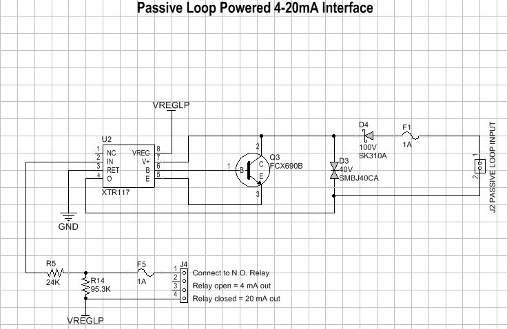
Here is the schematic in question.


This circuit is to add 4-20 mA loop interface (source side) option to an existing product that monitors the state of an industrial environment. Data is a simple binary state, 4 mA = ‘nothing is happening’ and 20 mA = ‘that thing I watch for happened’. The monitor device already features an isolated mechanical relay so I chose to use that switch to drive the XTR117. As you can see Vreg runs through R14 & R5 to IN that 4 uA causing XTR117 to output 4 mA. When the monitored event occurs the relay shorts out R14 and the higher current causes XTR117 to output 20 mA until the relay is opened after 5 seconds. The node labeled GND connected to Iret is “intended” to be isolated per the repeated warnings in the literature.

Therein lies todays challenge. The circuit as drawn works fine, as long as I leave the ground clip of my oscilloscope attached to GND of the XTR117 circuit. I would expect violating the isolated nature of the Iret local ‘ground’ with the oscilloscope’s ground would break the circuit rather than allow it to work. When the ‘scope ground clip is disconnected the loop current goes to 28.x mA, which I assume is the device limiting at its max. In that state changes to Iin can only change loop current by a fraction of a mA.

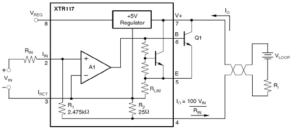
The following drawing from XTR117 data sheet helps further illustrates how I am working with the circuit.


On my test bench Rl is a 600 ohm power resistor. The battery labeled Vloop is a bench supply set to 24 VDC, in series with it and Rl is a current meter monitoring the loop current. As mentioned in TI literature when I connect the scope ground to the Iret GND node this allows a connection via their power supplies between Iret and that supply standing in for the Vloop battery in the drawing above.

My working theory is the voltage shifts observed when scope ground meets Iret GND pulls the inverting input of A1 to a level where the circuit works. I would like my theory a lot more if connecting scope broke the circuit rather than fixing it! Beyond getting this first article working this raises concerns of circuit stability when deployed to conditions more hostile than my lab bench.

All comments and hints welcomed.

  • Hi Norman,

    Your circuit design is a simple and effective way to create a binary 4/20mA output for a 2-wire transmitter design.  I've attached a simple simulation model to this message that you can use with the free simulator "TINA-TI" to see test the basic behavior of this circuit.  Please note that the simulation model uses ideal op amps and is only useful in understanding the basic operation of the system.  None of the XTR117 device related specifications in the datasheet are included in this model. 

    Isolated systems often create odd results when there are unexpected GND paths back to the chassis or supply connections and it sounds like something of that sort is occurring.  As you mentioned if you short the IRET pin of the XTR to the same potential as the RTN or any other hard potential relative to the RTN (GND) the XTR will fail to behave as desired and may be damaged.  If you short the "GND Short" switch in the simulation file you'll see that the circuit fails to operate.   Since your circuit only works with the scope GND connected to it something strange is going on and we'll need a little more information to determine what's going on.  Try using two oscilloscope channels with both of their GNDs connected to the +24V supply GND and put one on IRET and use the other to probe any nodes you're curious about in the circuit such as the VREG voltage the input voltage to the transmitter between the 24k and 95k resistor.  Then you can use the MATH functions in the scope to subtract the IRET voltage from the other voltage to see what the voltages in the circuit look like relative to IRET.  This will also provide indication if the IRET node and/or VREG nodes are getting pulled to an undesired potential relative to the supply GND return when the relay opens and closes.

    Also, what type of sensor transmitter are you trying to design (2-wire, 3-wire, 4-wire)?  The design you've shown will function as a type of input isolated 2-wire transmitter as long as the relay is completely floating and is not connected to any type of chassis GND or other potential.  

    Can you provide the full system schematic showing all connections to chassis or any other potentials?  If not, is anything else connected to VREGLP, or GND in the schematic you attached?  Is there any chance that some part of the relay is connected to a chassis GND or other potential?

    XTR117_relay.TSC

  • Hello Collin,

    Thanks for the quick response; we are certainly learning “Isolated systems often create odd results when there are unexpected GND paths back to the chassis or supply connections”.

    I tried the bench technique suggested using two oscilloscope channels and the math function to create a floating differential voltage measurement capability. Yesterday afternoon that did not work out, I ran into something of a real life Heisenberg principle in that connecting the scope ground to +24V supply GND with one channel on IRET resulted in the circuit ‘stuck on the rail’ in this case being outputting the max current 28 mA into the loop. I will repeat an attempt to run such a test with the scope AC ground lifted later this afternoon.

    I was able to make measurements using a battery powered multimeter which I will present below. You will note I have also revised the circuit adding a voltage follower op-amp as seen in many example circuits. I was testing if given that everything connected to Iin must be referenced to Iret that with its feedback an op-amp connected between Vreg and Iin will keep voltages between those limits and perhaps less effected by parasitic currents. This circuit behaved as the simpler passive resistor string into Iin version above did, i.e. stuck at current limit floating and able to output 4 or 20 mA with scope ground connected to Iret node.


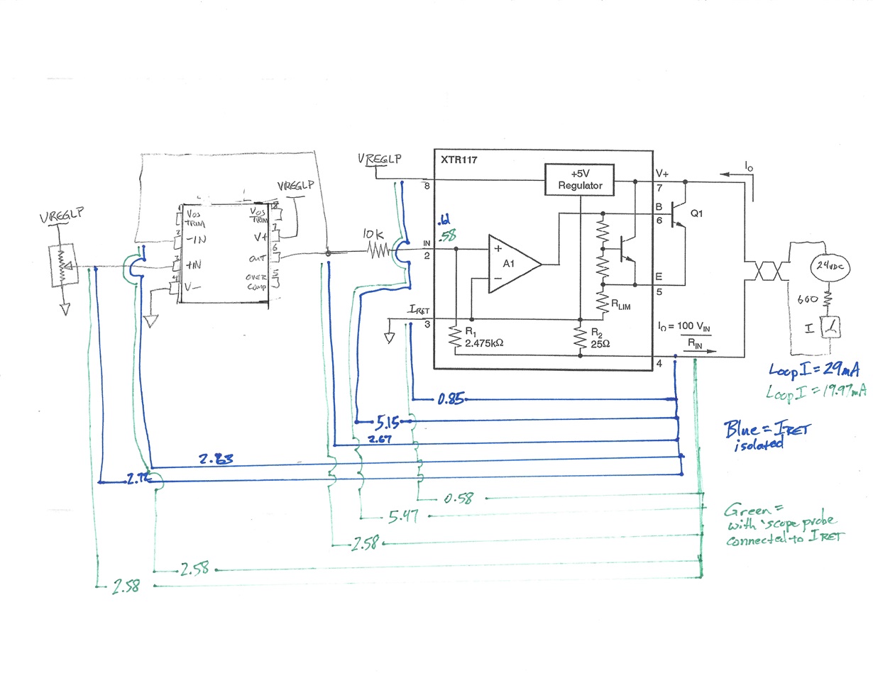
    Diagram shows voltage measurements made with floating battery powered multimeter. Ground probe at XTR117 pin 4 Iout, positive probe at node indicated. All triangular ground symbol nodes connected to Iret pin on XTR117. Numbers recorded are all DC volts. Green numbers show circuit connected to 24 VDC supply and Iret node connected to scope ground. With scope ground connected pot adjusted to output 20 mA on loop prior to making measurements, pot setting not changed for ‘blue’ measurements. Blue numbers show circuit connected only to 24 VDC supply. Comparing the two states one notes ~0.3 VDC shift in VREGOUT and Iret voltages. Also the expected balance at internal and external op-amps inputs when correctly functioning (green) and an imbalance at those nodes when circuit is stuck at current limit (blue).

    You asked and commented “Also, what type of sensor transmitter are you trying to design (2-wire, 3-wire, 4-wire)? The design you've shown will function as a type of input isolated 2-wire transmitter as long as the relay is completely floating and is not connected to any type of chassis GND or other potential.” The design is for a 2-wire not to be connected to any potentials other than the two loop wires.

    You also asked “is anything else connected to VREGLP, or GND in the schematic you attached? Is there any chance that some part of the relay is connected to a chassis GND or other potential?” Given the issues we are having getting this part of the circuit to work I have stripped off all other circuits. My hand drawn schematic includes the 24 volt power supply, load resistor, and meter that complete the test bench configuration.

    Other suggestions welcome. Do you believe the version of the circuit with the follower op-amp will be more reliable than the original simpler resistor string? My present plan is to continue bench testing looking for the illusive leaking ground.


  • Hello Collin & E2E community,

    For most of us Monday’s are not our favorites referenced to the weekend. A breakthrough in a sticky problem made on a Monday morning can take away some of the sting, I am currently enjoying such a moment.

    After posting the voltage measurements above I tried replacing the PCB connection of the Iret XTR117 pin 3 local isolated ground with an ‘air-wire’ connection to investigate PCB layout issues. This had no effect; circuit remained stuck at maximum current limited output. Out of ideas I reviewed the parts datasheet and application notes. It was on TI reference design “Digitally Calibrated Bridge Sensor Signal Conditioner with 4mA to 20mA Current Loop Output” SLAU526 by Ian Williams & Iven Xu that I first noticed C8 a 10 nF cap between LOOP+ and LOOP- and Q1 XTR117. Then reviewing the XTR117 datasheet the cap there called ‘Cout’ is shown on Figure 1 and Figure 3 but not on Figure 5 or the simplified typical application diagram on page 1.

    Adding a Cout to my implementation of 15 nF (no 10 nF on site) and the circuit instantly settled down operating as designed. Success!

    Now let us discuss why Cout appears to have fixed my circuit. I find no mention of that element in the data sheet’s ‘Applications Information’ section, reference designs, or blog posts. It is shown in the example circuits more often than not. Also on page 4 of the datasheet the first typical characteristics graph shows Cout + Rload impedance having the effect of reducing high frequency current gain.

    So is Cout stabilizing the current amp/regulator formed by XTR11x/Q1? Or is it acting as a local decoupling element across XTR117’s pins 4 (Iout) & 7 (V+)? Reducing high frequency gain looks like a classic method of stabilizing an amp or regulator. On the other hand XTR117’s pins 4 & 7 are about as close as we get to the typical analog IC’s ‘power’ and ‘ground’ nodes AND this ‘ground’ has in series 100s of ohms thanks to the loop impedance making it look like a pretty good spot for a decoupling capacitor.

    I want to dig into the Cout issue both to satisfy my engineering curiosity but more immediately important to gain confidence the value selected for Cout works in a wide range of circumstances out in the real world.

  • Hello Norman,

    I'm glad your Monday is going well, a little success in the lab goes a long way especially with strange issues like this one.

    The 10nF decoupling/bypass capacitor is definitely a requirement for proper output stability and operation of the XTR11x devices.  I've worked on a few other applications that described the same issue where the output was railing to the maximum amount and in those cases the decoupling capacitor was either not present or was located remotely from the XTR11x device.  If you put the scope GND on the power-supply GND and then probe the output pin of the XTR117 op amp (B) I'm pretty sure you'll see a sine wave indicating the circuit is completely unstable.  (I'll speculate at the end about why I think the scope is helping when connected to IRET)

    As you've guessed the capacitor reduces the bandwidth of the transmitter which helps compensate for the inductance of the wiring or any capacitance on the input circuitry that may lead to stability issues in the system.  The capacitor should be mentioned in the datasheet but sometimes the datasheet writers forget to include some of the simplest information about products because they're focused on the more advanced performance metrics and application subjects.  I did try to include it in all of my blog circuits, but I didn't explicitly mention it in any of them.  Maybe that's a topic for a 7th blog in the 2-wire series.

    As long as we're on the subject, the capacitor also helps with ESD, EFT, and radiated / conducted immunity performance which is desired in many 4-20mA applications. 

    Now as to why the circuit worked when the scope GND was connected.... This one is still a little perplexing but my best guess is that there's some capacitance from the earth connection on the scope GND to the line and/or neutral ac supply lines which eventually gets back to the ac power-supply for the XTR circuit.  This is maybe performing some type of similar bandwidth reduction in the transmitter that's allowing the circuit to function.  Since you're using a floating power-supply there's not a hard short between the power-supply GND and the earth'ed scope probe GNDs so there aren't any major dc circuit issues and it operates as desired (although there may still be some sneak paths that are affecting the output current at a low-level).  If you short the negative power-supply output to Earth and then try to connect the scope GND to IRET the circuit will fail to function as described in the blogs because the scope GND and power-supply GND are now shorted together.

    I hope that provides a little insight into what was happening in the circuit.  In the end you did have a type of Heisenberg situation where your efforts to view and debug the circuit accidentally compensated the circuit and cured the issue that was causing the circuit to operate incorrectly.  This prevented you from identifying the issue you were looking for.  :)