This thread has been locked.

If you have a related question, please click the "Ask a related question" button in the top right corner. The newly created question will be automatically linked to this question.

Using RCV420 for other current ranges

Other Parts Discussed in Thread: RCV420, ISO122, OPA140, TINA-TI

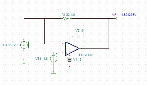
Is it possible to use the RCV420 for other current ranges other than 4-20mA and 0-20mA? I have a temp sensor that has a very uncommon output of 298.2uA @ 25C with a 1uA/C change. So the current range of interest is 218.2uA to 423.2uA. I would like to get a 0-5V analog output from this range.

I tried calculating the parallel resistors to adjust the gain of the system with the current range above but the resistor came out negative...


Thanks

  • Hi David,

    While we could likely adjust the RCV420 to accept slightly different input current spans than 0-20mA, the range you've mentioned is significantly different and we should probably look at other solutions.  

    Have you considered using a transimpedance amplifier with a negative offset? See below.  The circuit may not work depending on how your sensor needs to be connected, but provide a little more information and we'll work to figure something out.

  • Thanks Colin for the clarification. That was my initial thought just by my initial calculations and looking more at the adjustment features of the device, there was not too much documentation on what the capabilities was so for it. The temp probe that we are using is the analog devices AC2626. It is a 2-wire device, 1 for 24V PWR and 1 for SIGNAL.

    I have not looked at a transimpedance amplifier. Current, it is implemented as shunt resistor of 10k to get a voltage range between 2.982V to 4.322V and then isolating the signal using an ISO122. Then goes into a 2nd order LP filter, then to a DAQ system. I assume the DAQ is reading the direct range above.

    Is there an advantage between just a shunt resistor and then using the transimpedance amplifier?

    Thanks

  • Hi David,

    Either circuit will work fine for the current measurement, it probably depends more on how the sensor needs to be biased for proper operation.
  • Hi Collin:

    The temp sensor gets 24V on it's supply and spits back a range of 218.uA to 423.2uA (-55C to +150C). No special biasing is needed for operation.

    Instead of 0-5V, we have decided for a 0-10V output if possible.

    Thanks
    -David
  • Hi David,

    After looking over the datasheet for the sensor I think we should terminate the sensor into a resistor and then amplify/offset the output to achieve the desired range. 

    Try the circuit below.  It takes the sensor output, terminates it into a 1kOhm resistor and then offsets and gains the voltage across the resistor to 0-10V.  While I continued to use the OPA140, any dc accurate op amp that supports the power-supply range will work here.  You can open the simulation file if you download the free simulator, TINA-TI.

    Offset+Gain.TSC

  • Hi Colin:

    Thanks this looks fairly good. I took a look at it in TINA-TI. I tried modifying so that instead of a 1k shunt resistor, I was seeing what would happen with a 10k. With that, I get a range from 2.182 to 4.232V. I would assume then the offset needs to be ~2.182 voltage and the gain would be at 4.87 (0-10V scale / 2.05V scale). But it looks like there is some issues with it, in the sense that my output is from 2.18-12.17V. RF = 414.09k, and RG = 107k

    As I adjust the offset (just used a source rather than resistor divider to test it), I need to be around 2.74.

    Does that sound right? It seems like it is very sensitive in what the offset it, and maybe the parameters of the OP AMP are affecting it?

    Any explanation of this would be helpful!

    Thanks

  • Hi David,

    The circuit I proposed provides a positive gain and negative offset to the sensor output to convert the ~218.2uA - 423.2uA to a 0-5V output.  Terminating the sensor into a 10k load results in a much bigger offset (218.2mV vs. 2.182V) which makes the circuit component sizing a little easier. 

    If you want to change the input signal to the design then you'll need to change all of the components, (R2, R3, RG, RF), not just RG and RF.  I also don't recommend using a  non-standard reference voltage (i.e. 2.74V) because it will be hard to generate accurately.  It's better to start with a standard reference voltage (2.5, 4.096, 5, 10, etc.) and adjust the R2, R3, RG and RF component values to achieve the desired output range. 

  • I was proof reading what I just posted and I meant to state that the bigger offset created with the 10k termination will make component sizing harder, not easier. 

    Unless there's a reason based on the sensor datasheet to use the 10k load then I would use the 1k load and the circuit I provided previously.