This thread has been locked.

If you have a related question, please click the "Ask a related question" button in the top right corner. The newly created question will be automatically linked to this question.

Driving 800 nF capacitive load (piezo) by OpAmp

Other Parts Discussed in Thread: LM8272, LM8261, TINA-TI
A capacitive load of 800 nF (a piezo actuator) has to be driven with a step function. For example: first step 5V and 4 following steps of 1.0 V each. Slew rate 1 V/ms. 
After reaching the maximum voltage (10V), the 'capacitor' needs to be discharged within 10 ms (Vin = 0V), 
but that may be done by an additional comparator and FET if not possible by the OpAmp.
From the maximum output current, an OPA209 or OPA192 may be suited for a resistive load, but I expect not for a capacitive load.


Any recommendation which OpamAmp may be better suitable? There will be a +12V single supply. Required output 0 to 10V The OpAmp will be driven from a 12 bit DAC, preferably with internal reference like a TLV5636. In this case the OpAmp is in a non-inverting configuration with a gain of around 2.5

  • Hello,

    A possible candidate is the LM8272 which is "Unlimited Capacitive Load" capable.

    Here is a plot with up to 20nF cap load where the output slew capability is set by output current capability of +/-100mA:

    SR = 100mA / CL = 0.125 V/us for CL= 800nF (or about 80us for 10V transition across 800nF).

    This plot shows stability with up to 100nF:

    Since you only need about 1V/ms output slew capability, you could possibly use an isolation resistor between the driver output and the piezo device. If you used for example 100ohm isolation resistor, the full transition would take about 0.4ms (~5RC time constant) which is well within the 10ms that you have stated.

    Regards,

    Hooman

  • Hello,

    and many thanks for the suggestion.

    I already considered using a an isolation resistor, is a 'small' capacitor in parallel to the feedback resistor to mimize overshoot also worth to consider?

    When looking at the simplified schematic, it seems that discharing the 'capacitor' will also be possible within the time needed, or any protection rquired?

    I entered the parameters (non-inverting, Vsupply:0, 12 V, Vin:0 ... 4.096V, Vout: 0 ... 10.0V) in the WebBench form of the LM8272 page, but got the result that the devices is not suited for this application ...

    In the datasheet two caps are recommended a 0.01µF ceramic and a > 4.7µF Tantal or Aluminium. With the availability of 10 µF MLCC in 1206 package, are these also a good choice if space is limited?

    Are the LM8261 and SM73301 functional equivalent alternatives if a larger package is favorable?

    Regards

  • Hello,
    Yes, a capacitor across the feedback resistor is sometimes a good compensation against excessive capacitive load. The reason for instability with a large cap is the open loop output impedance of the driver which together with the large load capacitance, introduces phase shift in the loop gain which if large enough, causes instability. Depending on the case, a cap across the feedback cancels some of the phase shift.

    I have not worked with Webench. In this case, you are probably better off with building a prototype, or the next best thing working with TINA-TI which has the LM8272 and LM8261 pspice models built-in.

    I don't have enough experience about the MLCC in 1206 package capacitors to comment about their performance. Sorry. However, in your case, any possible instability may be more related to the phase shift issue I explained than any decoupling capacitor performance.

    I do not see much difference between the LM8261 and the SM73301 you have quoted. However, these devices are in two separate internal groups and I'm going to contact these to find any differences. If I find something significant, I'll post a response here.

    Regards,
    Hooman
  • Hello,

    using TINA-TI may also be a good idea to find a suitable value for the feedback capacitor value.

    I was mainly interested to get a comment if a LM8261 (or SM73301) can be used instead of the LM2872 you have suggested in your first response.

    Best regards,

  • Hello,

    Yes, the LM8261 has similar functionality / capacitive load drive tolerance, but it delivers less output current. However, your application requires 1V/ms ramp rate across your load, which the LM8261 should also be able to deliver.

    Regards,

    Hooman

  • I have made a TINA-TI simluation now:

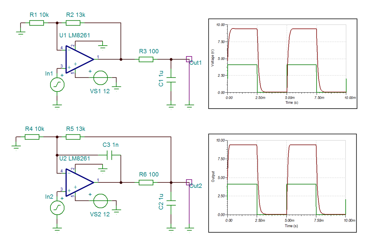
     The upper curcuit is like the one we have discussed showing the results predicted by you.

    For comparison I have added a feedback capacitor and connected the feedback resistor R5 to the capacitve load C2.

    There is no big difference in the simulation result, except that the small overshoot in the upper circuit has disappeared.

    Any comments if the circuits can be made better?

    One other point which is not clear to me: In my understanding, both circuits are inedependent of each other. But when running Transient analysis, I do got a different resulty for Out1 after adding the lower circuit  and if changing the value for C3 for example ...

    Regards,

  • Hello,

    Both LM8261 circuits look to be stable. But, this is only simulation and you may find instability once you build the circuit.

    What you are doing with the lower circuit is called "in-the-loop compensation".  It is meant to provide a dominant feedback path at high frequency through the small feedback capacitor from output to the inverting input. This article provides some guidelines on how to choose the values of the compensation components:

    To apply the equations derived in the application note above on page 2, for the LM8261, use about 15 ohm for the value of open loop output impedance (Ro). Here is what I compute for your conditions (RF= 13k, RIN= 10k, CL= 1uF, Acl = 2.3, Ro= 15ohm):

    • Rx= 11.5ohm
    • Cf= 2.9nF

    You may want to try these values in your circuit.

    Regarding your other point: I have no idea why adding the lower circuit to your TINA-TI simulation file caused the upper circuit response to change! You could experiment with "TR excitation subdivisions" as noted below:

    Regards,

    Hooman

  • Thanks for further comments, I will look at real life circuits.

    Regarding TINA TI: I have increased  'TR excitation subdivision' as suggested, but still the same issue: If C3 in the lower circuit is increased from 1n to 100n , the Out1 changes too. If there is a chance to send the .tsc file I will do so.

    Best regards,

  • Hello,

    To attach a TINA-TI tsc file, all you do is click on "Use rich formatting" and there you will see the button for attaching files to the post, as shown below.

    Regards,

    Hooman

  • Hello,

    I see the problem with your TINA-TI simulation file that causes the upper circuit waveform to change with whether or not you have the lower circuit on the same simulation file.

    You had labelled a node "VG1", which when you copied, and pasted to create the lower circuit, remained the same name and thus was an inadvertent connection between the upper and lower circuits! Here is the TINA-TI image showing this unwanted connection:

    Here is the netlist highlighting the VG1 connection that needs to be broken:

    LOWPIEZO NETLIST.docx

    To correct the issue, delete the lower circuit all together, delete all connections to U1 inverting input (including R1, and R2). Then place R1, and R2 again, and connect to U1. Without renaming any nodes, copy and paste the upper circuit to create the lower circuit, and edit as needed. This would ensure that the two circuits are independent.

    This modified TINA-TI file breaks the connection between the two halves and does not suffer from the issue you're having:

    LowPiezo Recreated 5_27_16.TSC

    Regards,

    Hooman