This thread has been locked.

If you have a related question, please click the "Ask a related question" button in the top right corner. The newly created question will be automatically linked to this question.

Photodiode Transimpedenace Amplifier

Other Parts Discussed in Thread: SM73302, OPA320

Dear all,

I want to know it is required to have a feedback capacitor to stabilize the circuit, since my operating frequency is only 100 Hz.

  • I am using SM73302 precision amplifier.
  • Circuit is a simple Photo voltaic circuit.
  • Feedback resistor is 1Meg.
  • Current Range to amplify is 17nAmps to 0.17nAmps.
  • A 24 bit differential ADC 40mv to (-40mv) is also used after amplifier.

I have attended training in Noise, stability and Bandwidth videos of precision lab by Art kay, Ian williams, Tim Green and Collin Wells.

  • Hello Srikant,

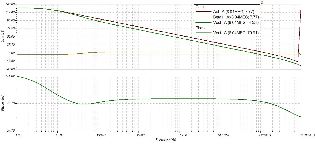
    You will still need a feedback capacitor to stabilize this circuit.  The circuit stability is based on the noise-gain (non-inverting gain) of the circuit , which is different from your signal gain.  So even though you only care about signals up to 100Hz, the circuit may still have significant stability issues at the frequency where the loop-gain (Aol*B) = 0dB which is where the circuit phase-margin is measured.  The circuit stability problems will affect your circuit performance at 100Hz in the way of high overshoot/ringing and possibly undamped / unbounded oscillations.  My colleague John Caldwell published a really great blog series and reference design about transimpedance amplifier design.  I only linked to part 3 of the blog series because a .PDF version of parts 1-3 of the blog is included at the end of part 3.

  • Hi Collins,

    Thank you so much for guiding, your suggested blog series really helped me.

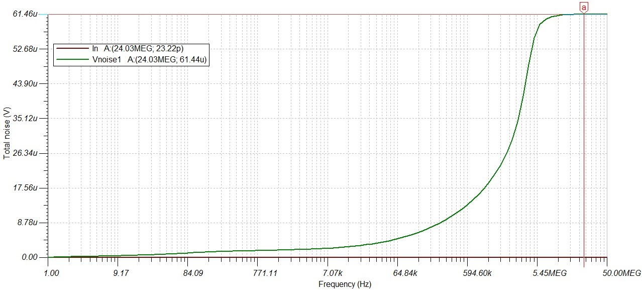
    I have attached my  circuit diagram and its noise and stability diagrams.

  • Nice work Shivank!

  • Hi there,

    I am having problem in supply of OPA320. I am using LM336 reference diode for the supply of 2.5v and -2.5v.

    Problem is when I connect LM336 output to V+ of OPA320 it is giving only 0.6v and varying with resistor values. At 470ohms it becomes 2.49v. Same for negative supply voltage (V-). It should be stable.

    And when I disconnect LM336 o/p from op amp it gives correct and stable output(from resistor 470ohms -10k), I don't know why this is happening.

    For negative supply i have used 555 astable and charge pump circuit and LM336 reference diode. Also using supply voltage of 5v and converting it 2.5v from LM336.

  • Hi Shivank,

    I'm guessing that the LM336 doesn't support the output currents required to supply the OPA320 positive supply and the 555+charge pump circuitry (which then supplies the negative supply to the OPA320). The LM336 is designed to be a precision voltage reference and you're using it more as a voltage regulator. You should probably look into a dedicated low-dropout voltage regulator (LDO) to perform the operation you're looking for. An LDO will provide higher output current capability at a possible cost reduction compared to a precision reference. Consider a product in the TPS7A4xxx family.