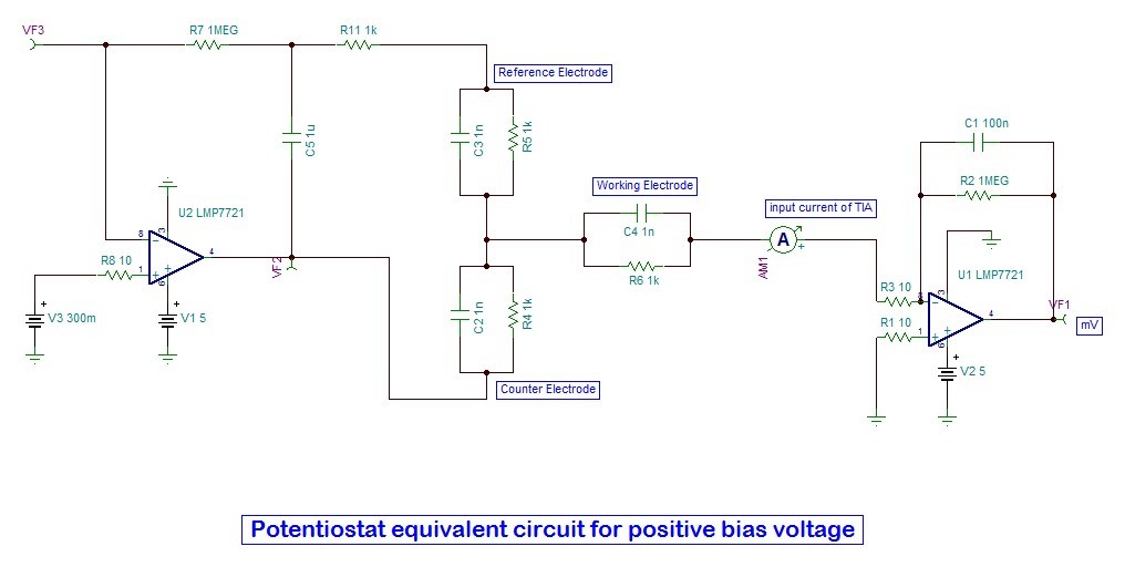
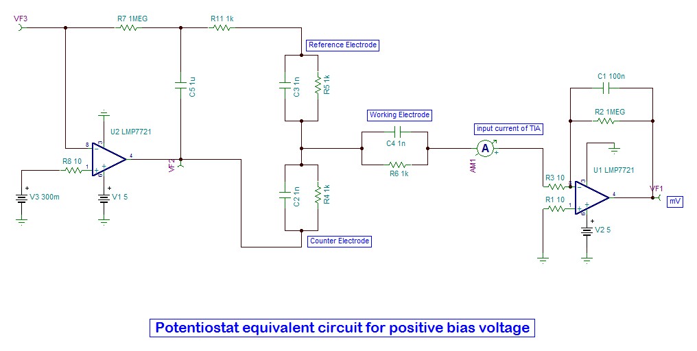
This thread has been locked.
If you have a related question, please click the "Ask a related question" button in the top right corner. The newly created question will be automatically linked to this question.
Hi Nirav,
You need to add a current source in the working electrode to create the sensor "current".
Right now you are creating a inverting amplifier with a gain of 1000, with an input of 300mV, which is railing the output of the "TIA" against ground.
Regards,
Hello Paul Grohe,
This is a equivalent model of three electrode potentiostat. I have put impedance, in term of resistance and capacitance, of working electrode (WE), Reference Electrode (RE) and Counter Electrode (CE).
Actually, the sink or source current may be generated due to the concentration of electrolyte and bias voltage in potentiostat.
Due to 300mV bias voltage, the AM1 shows the -324.53 nA and provide 75.51 mV output at VF1.
I have simulate the same circuit with external current source to TIA with same feedback and I have found that from +300 nA I am getting 300 mV and so on, as it is true because the gain of TIA is 10^6 (as 1 M resistor used in feedback).
But due to negative current and less than +300mA, I am getting just 75.51mV.
I am not getting the logic behind it.
Hello Paul,
I got your point.
As I am working on three electrode potentiostat, as shown in attached file, in which working electrode may sink or source the current and TIA is use as I2V convertor.
I have post the tina simulation which is equivalent circuit of three electrode potentiostat.
Vbias is the voltage what we need to provide on reference electrode and its range is -500 mv to 500 mv.
According to bias voltage, due to concentration of electrolyte, few uA or even less current may sink or source in working electrode.
It needs to convert in equivalent mV by TIA, which further measured by ADC and LCD.
Potentiostat Equivalent Circuit for positive bias voltage - autosave 16-05-24 17_40.TSC