This thread has been locked.

If you have a related question, please click the "Ask a related question" button in the top right corner. The newly created question will be automatically linked to this question.

ECG_RA and ECG_LA feature input signals: type, amplitude, frequency, (detailed description)

Other Parts Discussed in Thread: TINA-TI, INA826, INA333

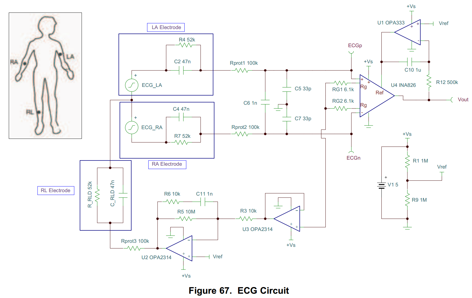
In the figure above, in TINA-TI SPICE simulation program, I want to know what type of signal is set to ECG_LA and ECG_RA in the circuitry that corresponding to LA and RA  Electrodes, and are marked in the two corresponding boxes.

Thanks for the help, MariusROSU

  • Hello MariusROSU,

    The boxes contain the equivalent model for the signals from the left arm (LA) and right arm (RA).
  • Hello, Good morning Pete Semig,

    I don't think you get the exact meaning of my question, or I have not made it pretty clear; I know that the two rectangles represents equivalent electrical circuit model for LA and RA electrodes, but the essence of the question was what type of signal should be set-up for the two voltage generators, denoted ECG_LA and ECG_RA, such that at the exit denoted Vout (pin 7 of OA INA826), the signal to be relatively close to a real EKG.

    A modified circuit, but with the instrumentation amplifier INA333, is already done by me and tested in real conditions; now I want to determine some characteristics of power consumption through simulations.So I repeat, the goal is not what the rectangles represent, but what kind of signal or function must be set to ECG_LA and ECG_RA.

    Thanks again,

    MR

  • Hello MR,

    Thank you for the clarification. There is a TINA-TI simulation called ECG_External.TSC in the following forum thread:

    e2e.ti.com/.../117436

    Please download TINA-TI and open the simulation. You can then double-click on the ECGp and ECGn sources. Then click in the Signal section as shown below:


    This will open the following dialogue box which shows the X and Y values of the piecewise linear source as shown below.

  • Hy, good morning,

    Yes it works, but for my circuit I have to revise some values in the signal lines and maybe of passive components, according with the picture below

    Thanks,

    MR

    Characteristics of the ECG signal_400.tif