This thread has been locked.

If you have a related question, please click the "Ask a related question" button in the top right corner. The newly created question will be automatically linked to this question.

PGA309 EVM issues

Other Parts Discussed in Thread: PGA309, PGA309EVM-USB

Hi Team,

The customer is using PGA309 EVM-USB. There are three issues.

Q1: When he connects PGA309 EVM-USB to PC, the default mode is one-wire and the EVM board can read the registers and calibrate. That is no problem.

But if he selects the IIC mode, all registers are " FFFF"  in "read all reg" window. What is the reason? How to solve the issue?

Q2: Can you explain the TEST pin function in detail?

Q3:  The customer refers the EVM schematic and he designs a board. And the EEPROM number is the same as the EVM board, that is 24LC16BT.

Then he uses the IIC mode to communicate with J1 of USB-DAQ-Platform. That is he uses SCL pin and SDA pin of PGA309 to connect 12 pin and 13 pin of J1.

But the board can't communicate with USB-DAQ-Platform. What is the reason?

If he uses one-wire mode to communicate with J1 of USB-DAQ-Platform, how to design the circuit? which pins should be connected for PGA309?

Thanks,

Best  Regards,

  • Hello Mickey,

    Please see my answers below.

    Q1: The PGA309EVM-USB only supports one-wire operation, as the software does not have code to support the I2C interface. 

    Q2: The TEST pin is used to allow full control of the PGA309 registers by a microcontroller or other digital programming device.

    • TEST pin voltage = GND (logic '0') = normal operation. PGA309 continuously reads data from external EEPROM and updates its registers based on the measured temperature and EEPROM lookup table. Any changes to PGA309 behavior must be achieved by writing to EEPROM.
    • TEST pin voltage = +VD (logic '1') = "test" operation. EEPROM readback is disabled and PGA309 registers can be written directly. PGA309 voltage output is permanently enabled.

    By default, the PGA309EVM-USB works with TEST = GND (logic '0') for normal operation. During calibration, data is written to the external EEPROM in order to cause changes to the PGA309 registers.

    Q3: Again, the PGA309EVM-USB software does not support I2C mode. Only one-wire mode is supported. If the customer uses one-wire mode to communicate with the circuit, I recommend following the schematics from the PGA309 User's Guide, copied below. Please note that the required connections change depending on whether 4-wire mode (PRG separate from VOUT) or 3-wire mode (PRG connected to VOUT) is used.

    Best regards,

    Ian Williams
    Linear Applications Engineer
    Precision Analog - Op Amps

  • Hi Ian,
    Thanks for your reply.
    Q1: If the customer wants to modify the registers value, the TEST pin should be high level. Have I understood correctly?

    Q2: If the customer wants to use one-wire mode, he should refer Figure 4-15 of PGA309 User's Guide, right?
  • Hello Mickey,

    Q1: If the customer wants to modify the registers value directly, the TEST pin should be high. However, the TEST pin can also be kept low and the EEPROM can be written. When the TEST pin is low, the PGA309 reads the EEPROM every few milliseconds and updates its registers.

    Q2: If the customer wants to use the 1W interface and a 3-wire module, with VOUT connected to PRG, he should refer to Figure 4-15. If he wants to use the 1W interface and a 4-wire module, with VOUT and PRG separate, he should refer to Figure 4-21.

    Best regards,

    Ian Williams

  • Hi Ian,
    Thanks.
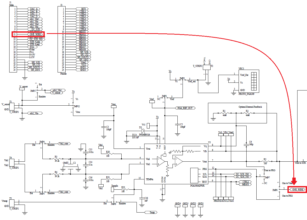
    Q1: The customer has another issue. He uses PGA309EVM-USB and he found one-wire is not be connected in the EVM board from sbou084a. Look the attachment.But you tell me the PGA309EVM-USB only supports one-wire operation. So which interface is used in the  PGA309EVM-USB board?

    Q2: However, I can not find sbou084a  document on TI website and I also can not see the PGA309EVM-USB on TI website now(8/25).  I still can see PGA309EVM-USB and  sbou084a  document on TI website a few days ago. What is happened?

  • Hi Mickey,

    Q1: The PGA309EVM-USB uses the one-wire interface. That table is incorrect. Please see the PGA309EVM-USB schematic, partially copied below. Pin 11 of connector J1 connects the ONE-WIRE signal from the USB-DAQ platform. The ONE-WIRE signal connects to the PGA309 PRG pin depending on the position of jumpers JMP7 and JMP8.

    Q2: That is very strange. It looks like the page for the PGA309EVM-USB and many of the documents can not be found on the website right now. I will investigate this.

    Best regards,

    Ian Williams

  • Hi Ian,
    OK. Thanks. I am waiting for the reply Q2.
  • Hi Mickey,

    The PGA309EVM-USB page was hidden by mistake. The team that handles the website has re-activated it now and it will be back tomorrow morning.

    Best regards,

    Ian Williams
  • Hi Ian,
    Thanks.