This thread has been locked.

If you have a related question, please click the "Ask a related question" button in the top right corner. The newly created question will be automatically linked to this question.

OPA564 Voltage follower / Current SINK

Other Parts Discussed in Thread: OPA564, OPA544, OPA548

Hi.

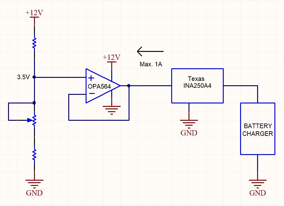
          I need to use OPA564 as a voltage follower with current sink capability. The circuit I am going to implement is based on SLVA618 "Building your own battery simulator", but less complex. I want to use OPA564 instead of OPA544 because the design is based on a single +12V supply, the charging current I need to simulate is 1A max. and the price is much lower.

          I know it´s a simple question, but I want to be sure that this amp is capable of sinking 1A while is acting as a voltage follower. I do not have experience usign op amps as current sinks. I have read the datasheet and I think this op amp is ok for my purposes, but I want to be sure. Could somebody help?

Thank you for your help!!

  • Hello Perico,

    Connecting a power op amp as a buffer with +3.5 V applied to the non-inverting input will result in the amplifier holding the output voltage very close to +3.5 V. If the battery voltage is greated than +3.5 V the op amp will sink to ground whatever current within its capability to bring the voltage down to +3.5 V. Similarly, if the battery voltage is lower than +3.5 V, the op amp will source whatever curren tit can to bring the output voltage to +3.5 V. Power op amps such as the OPA544 and OPA564 can deliver a 1 ampere output current, but the thermal capability of the device must be taken into consideration before applying it.

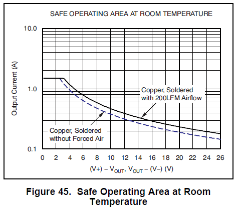
    Shown below is the Safe Area Operating (SOA) curve for the OPA564. The dashed curve indicates that for a continuous 1 ampere output that the maximum [(V+) - Vout] voltage difference is between 3.5 V and 4 V. Therefore, if the output is +3.5 V, the maximum supply volttage V+ should be kept toabout +7 V. The +12 V supply would result in too high of power dissipation unless the duty cycle could be much reduced from 100 %. If the OPA564 is cooled with a fan as indicated by the solid curve the voltage differential could be a little higher, but still doesn't do what you need.


    The OPA548 has a higher power dissipation capability than the OPA564, and its operating and output voltages are compatible with your circuit. Take a look at its datasheet and SOA curve. You can find the datasheet here:

    www.ti.com/.../opa548.pdf

    Regards, Thomas

    PA - Linear Applications Engineering

  • Hi. Thank you very much for your help.
  • Hi

    I am using OPA564 IC for my application to drive 10 ohm load with voltage gain of 2V/V in closed loop configuration. The input is applied at non- inverting terminal of opamp which is sine wave of 50kHz to 500kHz with 3Vpp (+/-1.5V) input. 

    I want circuit to work at lower supply voltages of 8V (V+ at 8V and V- at GND) and high voltages upto 15V.

    The problem is when supply voltage is of 9V, the output waveform is getting distorted (clipping). I have added dc shift of 2V at non-inverting input of opamp as the supply to opamp is positive ie. V+ at 8V and V- at GND.

    I want one clarification whether we can use it for lower voltages or not? And if yes, what extra changes are required.

  • Hello Pratima,

    Can you provide a schematic for your OPA564 circuit? That would be helpful for troubleshooting the problem. Please include input sources and the load in the schematic.

    Thanks, Thomas

    Precision Amplifiers Applications Engineering

  • Hi,

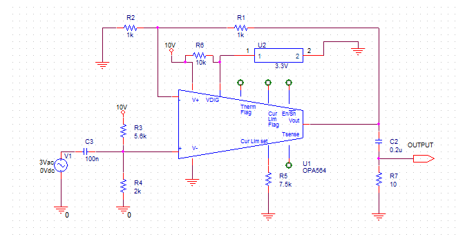
    I have included the schematic as shown in Figure below.

    As I had told that there was an issue of distortion at the lower voltages ie. at 9V supply. 

    I changed the output coupling capacitor from 1uF to 0.2uF, and the circuit works better at lower voltages of 9V and at lower frequencies.

    But some distortion is still there at frequencies above 300kHz. Highlighted by blue circle.

    Kindly suggest what needs to be done for lower voltages and for higher frequencies upto 500kHz.

  • Hello Pratima,

    It is normal for an op amp's distortion to increase as the input frequency is increased. That happens because the open-loop gain (Aol) of the op amp roles of with increased frequency. This Aol roll-off can be observed in the OPA564 datasheet Figure 13, GAIN AND PHASE vs FREQUENCY graph. Viewing the graph it appears that the Aol is only about 30 dB at 500 kHz. Then, it continues to drop as the frequency is increased. The benefit of the distortion reduction attributible to high Aol diminishes as the Aol becomes lower. The net result is increased distortion at higher frequencies.

    The OPA564 in your circuit has about +2.63 V applied to the non-inverting input. Since the circuit has a gain of +2 V/V the op amp output will rest at about +5.26 V, with no ac input. Once an ac signal is applied to the input the output sinks and sources current through the output coupling capacitor to the load resistance. Near the center of the of the swing you may observe crossover distortion. That occurs because the output stage sitches from one of the output transistors, to the other. This is typical of a class AB output stage.

    I am not sure what the actual ac input level is being applied to the OPA564 circuit. The dc level as mentioned is +2.63 V, but the op amp has a limited common-mode input voltage range, VCM, of V- to (V+) -3 V. If the VCM range is violated input distortion will occur and it will be observed at the output. However, with the gain of +2 V/V the output should be clipped if that were the case.

    Another source of distortion may be the capacitors you are using at the input and output. If you are using ceramic cpacitors having lower-cost, lower performance X7R, Z5U, Y5V, etc. dielectrics, they can exhibit a non-linear capacitance change with applied voltage. Thus, when the voltage changes across the capacitor its capacitance changes. We have observed increased circuit distortion increasing as a result of this characteristic. Using a quality film capacitor in place of ceramic capacitors should verify if that is an issue or not.

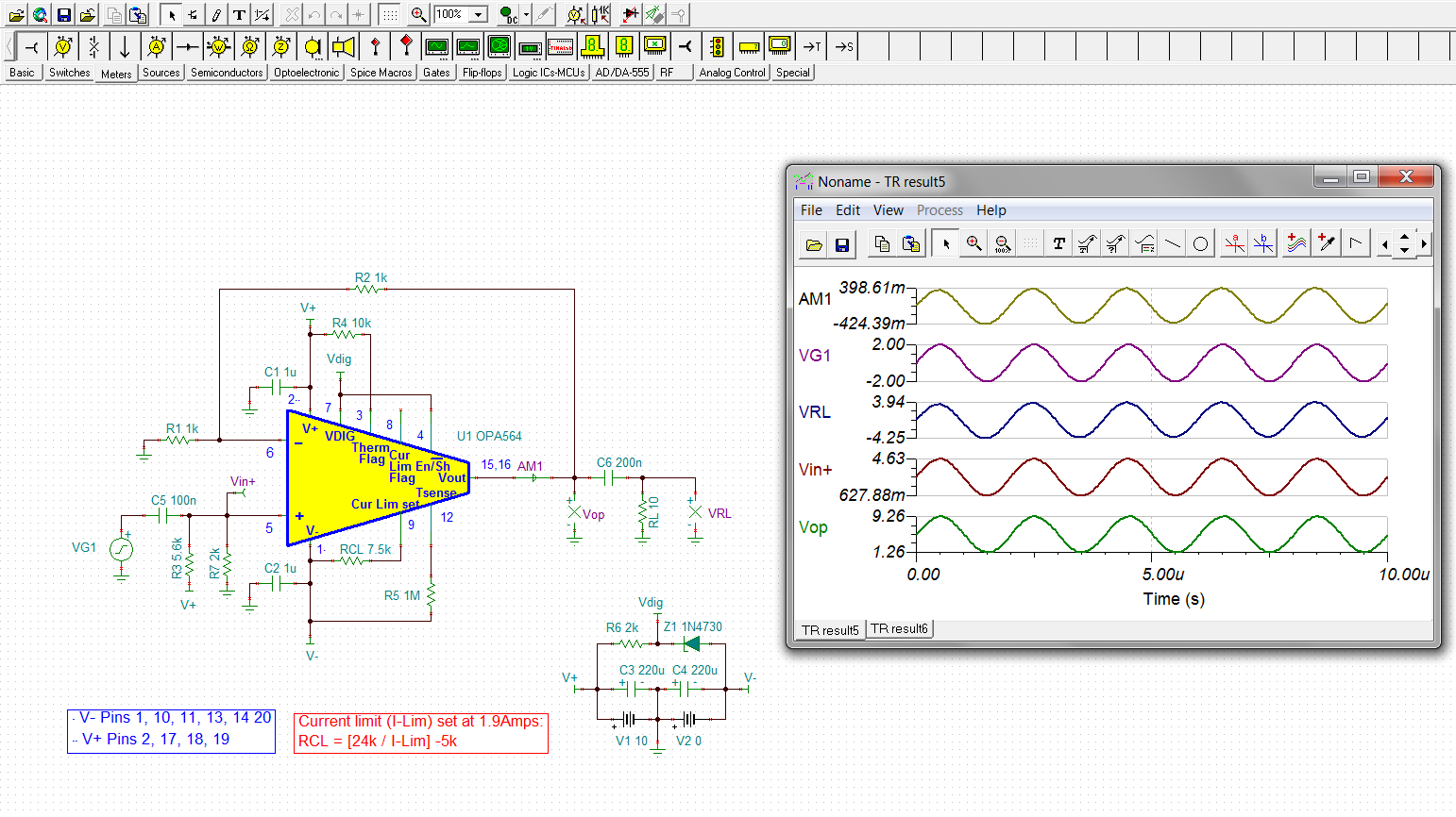
    I set your circuit up with the TINA Spice simulator just to check the signal levels. V+ was set to +10 V and with VG1 set to 500 kHz and a 2 Vpk input level, everything appears okay. You can see the results below.

    Regards, Thomas

    Precision Amplifiers Applications Engineering

  • Hi Thomas,

    Thanks for reply. I will try with the film capacitors to suppress the distortion.

    And will get back to you in case of any concern.