This thread has been locked.

If you have a related question, please click the "Ask a related question" button in the top right corner. The newly created question will be automatically linked to this question.

OPA454 failures

Other Parts Discussed in Thread: OPA454

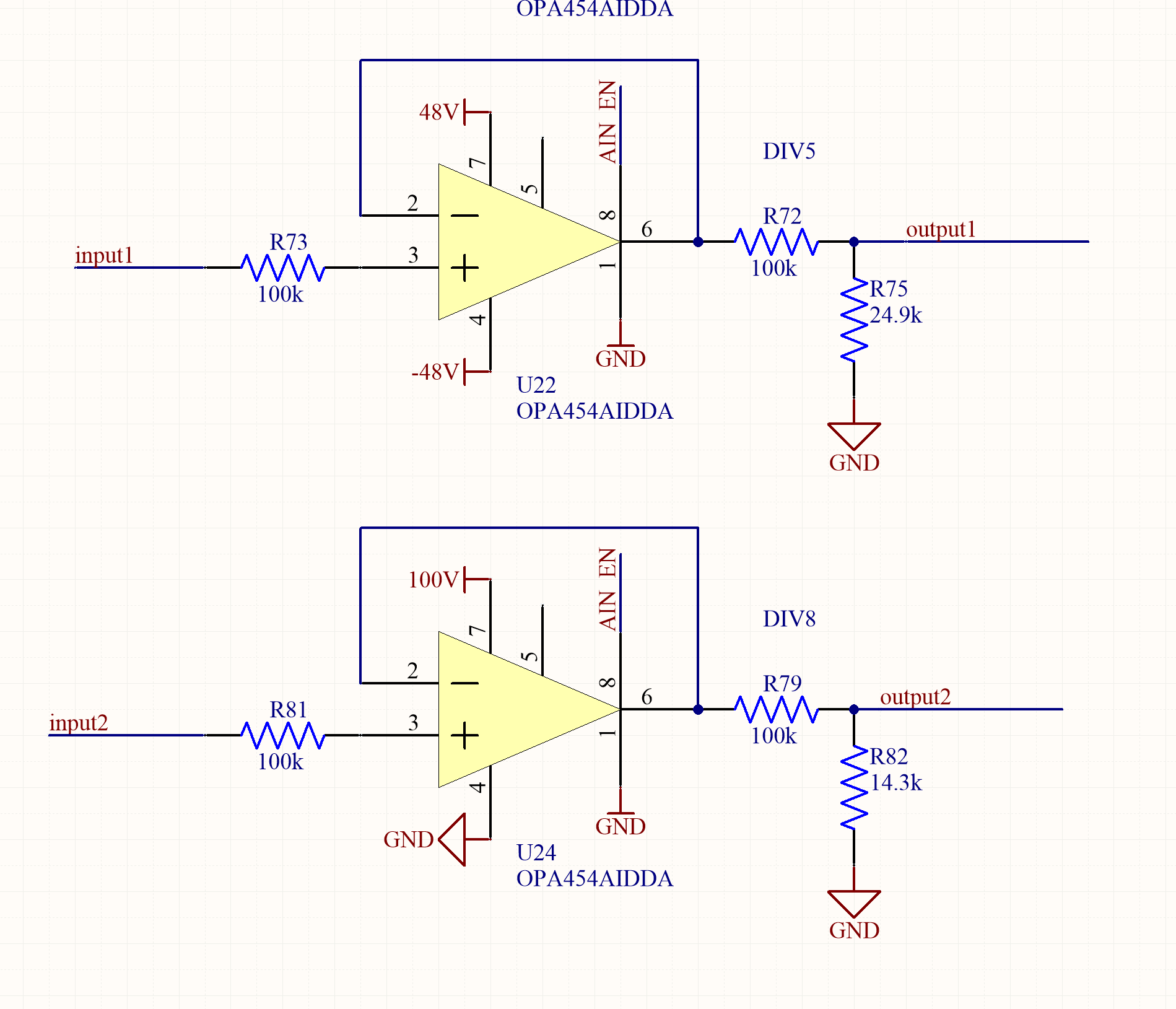
I've had several OPA454 parts fail in the same circuit, used to provide a high impedance input to a resistor divider in the position of U24 in the below schematic.

U22 has had no such failures. The difference is that U24 sees a different grounding scheme and input 2 can be up to 70V while input 1 is only 15V.

It is possible in this circuit to have input voltage with no supply voltage present, but there is a large resistor out front and I would think the internal clamping diodes should be able to handle it. 

Any thoughts on what could be damaging the parts?

  • Dear ebh,

    I'm moving this to the op amp forum. Someone there will gladly answer this for you.

    Thanks!

    Carolus
  • Hi ebh,

    On the surface the circuits look okay so something less obvious must be at work to lead to the failures. The OPA454 has a PowerPad on the underside of the package that must be connected to the V- supply level. It shouldn't be left floating so check that first. If it is left floating the electrical isolation between the circuits on the integrated circuit may be lost. Unexpected internal current paths can be set up in such cases. 

    Having +70 V applied to input2, without V+ present, might lead to an input latch condition upon V+ power up. But having a large series input resistor limiting the input current to a low level usually helps prevent latch-up from happening, but maybe with 700 uA input current it is happening.

    You mention that the devices are being damaged. Can you describe what kind of damage is occurring? Do they just start exhibiting a specific unexpected behavior, or are they critically damaged?

    Regards, Thomas

    PA - Linear Applications Engineering

  • The Powerpad is tied well electrically and thermally to V-.

    The parts are getting their supplies shorted (holding down the 100V supply after a power cycle of the supply). I measure 8.2 Ohms from pin 7 to pin 4 on a part we pulled after normal operation ceased.
  • Hi ebh,

    That result indicates that an internal circuit path between V+ and V- has broken down and shorted. It could be a path in the op amp core, or the supply-to-supply ESD protection device connected between the pins. If the ESD circuit is turned on by an EOS over-voltage the cell can latch and will conduct current until the circuit overheats and shorts. The ESD cells are not intended to ever be turned on under normal circuit operating conditions and are in place to protect against out of circuit ESD events associated with handling and assembly.

    I suggest obtaining some unidirectional transient voltage suppression diodes (TVS) and mount one between the V+ and V- pins, or to ground. Since your single supply is +100 V you will need a TVS with a reverse standoff voltage (VR) greater than than 100 V. Littelfuse has a TVS, part number 1.5SMC120A, that has a VR of 102 V and a reverse breakdown voltage VBR of 114 V minimum, 126 V maximum (IT = 1 mA). If the power supply is producing a high voltage transient at power turn-on of turn-off, then the TVS would clamp the transient and keep the OPA454 safe.

    Also, you don't shown any power supply decoupling capacitors in your simple circuit. I would exect that you have them in place.

    Regards, Thomas

    PA - Linear Applications Engineering

  • I tried adding TVS diode. The voltage is actually around 93V. I put on a SMBJ90D-M3/H which has a lower breakdown voltage, but doesn't drain too much current. and Yes there are decoupling caps in place.

    The amp hasn't had a catastrophic failure yet, but I'm seeing increased current draw on the input. Though the circuit is supposed to monitor ~60V, even my test signal of 5V is seeing several volt drop across the 100K resistor (R81).

    There seems to be excessive current draw on the op amp input. Any idea as to what to try next?
  • Hi ebh,

    So it appears that adding the TVS diode to the OPA454 supply pin has helped stop the V+ to V- failure from occuring, but now you are seeing the U24 input bias current creep up. The source of that issue may be difficult to determine.

    This is a precision amplifier application and we have seen a number of leakage current issues come about from PC board contamination. Residual solder flux remaining on the board sets up unexpected resistive paths between points in the circuit. The flux residue is not a stable material and its resistance can change with the applied voltage, temperature, humidity, etc. We run our analog EVM boards through an ultrasonic cleaner not once, but often twice to remove any remaining residual flux. In many cases doing so has resolved odd, unexpected, circuit performance anomalies. I suggest cleaning the PC boards as described and then seeing if the high input current deminishes.

    Also, can you tell me what the AIN_EN lines of U22 and U24 connect to in your schematic? Better yet, can you provide the schematic for the part of the circuit? If it is externally powered does its source come up before the V+ is applied to the OPA454?

    Regards, Thomas

    PA - Linear Applications Engineering