This thread has been locked.

If you have a related question, please click the "Ask a related question" button in the top right corner. The newly created question will be automatically linked to this question.

ALM2402A high impedance feedback resistors

Other Parts Discussed in Thread: TINA-TI

Hi,

I want to use the ALM2402A in a BTL configuration to drive a 32Ohm speaker, powered from a single 12V supply.

I used the TINA-TI simulation to test the circuit and I see that with 1K feedback resistors the circuit works fine and distortion is <0.5%.

If I increase the feedback resistors to lets say 20K the distortion increases to 5%.

Is the AML2402A not designed to handle higher value feedback resistors or am I dong something wrong here?

I tried to upload the schematic but do not see how I can do this.  I can send the Tina schematic by email.


  • Jan,

    Use this icon to attach file.

    What amplitude voltage peak to peak do you need for each amplifier? I'll assume 11Vpp

    The slew rate needed is pi * F * Vpp = 3.14 * 20,000 Hz * 11V = 0.68V/us

    This is faster than the typical slew rate of 0.17V/us


  • Ronald,
    The two amplifiers are in the typical bridge topology. The first amplifier is inverting with 10K feedback and source resistor, the output of the first amplifier is inverted by the second one.
    Feedback resistors of the second are also 10K, both positive inputs are connected to 1/2Vcc.
    The input signal is AC coupled at the 10K input resistor (- input of the first amplifier) with an amplitude of 8Vpeak-peak, Vcc = 12V.
    The load between the two outputs is 32Ohms (speaker) so with a gain of 1, the output swing over the load is 16Vpeak-peak.
    The maximum output current is 8/32=250mA. The ALM2402A is capable to deliver 400mA so should be OK.
    I used a 1KHz signal in Tina so the max slewrate is 3.14 * 1000Hz * 16V = 0.05V/us. With a max slew rate of 0.17V/us the maximum frequency should be 0.17e6/3.14*16=3.4KHz. The 1KHz test signal should be OK.
    Tina gives other results, the current limit seems to kick in at 240mA and the signal distorts up to 5%.
    Can you confirm that the ALM2402A can be used in a bridge topology as described above with 10K or higher feedback resistors, 12Vcc, 16Vpp out @ 32Ohms within the slewrate limits?
  • Jan

    I noticed that the model distorted with high resistors. I think this is a model problem.

    I can look into it later this week. I am travelling today.

  • Jan,

    I will test the circuit in lab this week.
  • Jan,

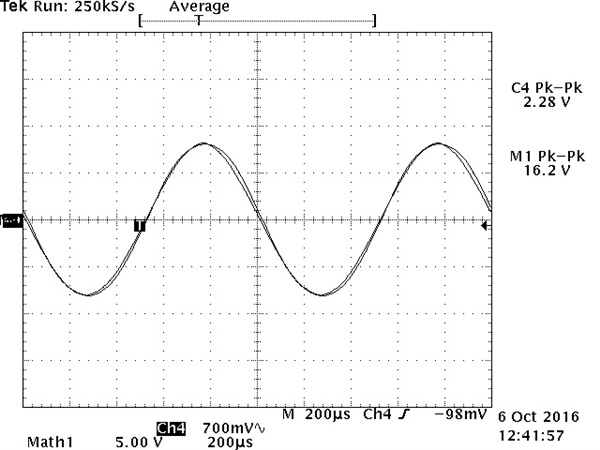
    I built the circuit with input  input R + C at 36k plus 1uF. All other resistors are 150k . Load is 31 ohms

    Here is the input signal and output load voltage. I set oscilloscope scale to line up waveforms as close as possible.

  • Ron,

    For another application we are looking to use the ALM2402 in a current source topology, driving a 10uH/3.5Ohm coil.

    Also here the Spice model gives other results than expected.

    The Tina waveform looks as if a current limit kicks in whilst the current is around 250mA, where the datasheet claims 400mA max drive current.

    Are there functions in the ALM2402 model that cause this other than a lower than datasheet spec current limit?

    Can you comment on this.

  • Jan,

    The images didn't work. Can you re-post them or email them to me?