This thread has been locked.

If you have a related question, please click the "Ask a related question" button in the top right corner. The newly created question will be automatically linked to this question.

Help with instrumentation amp selection

Other Parts Discussed in Thread: INA826

Hello,

I am having trouble with an instrumentation amp that is currently in my product.  Because this part has been so hard to work with I am looking at replacing it.  I was thinking about trying the INA826. 

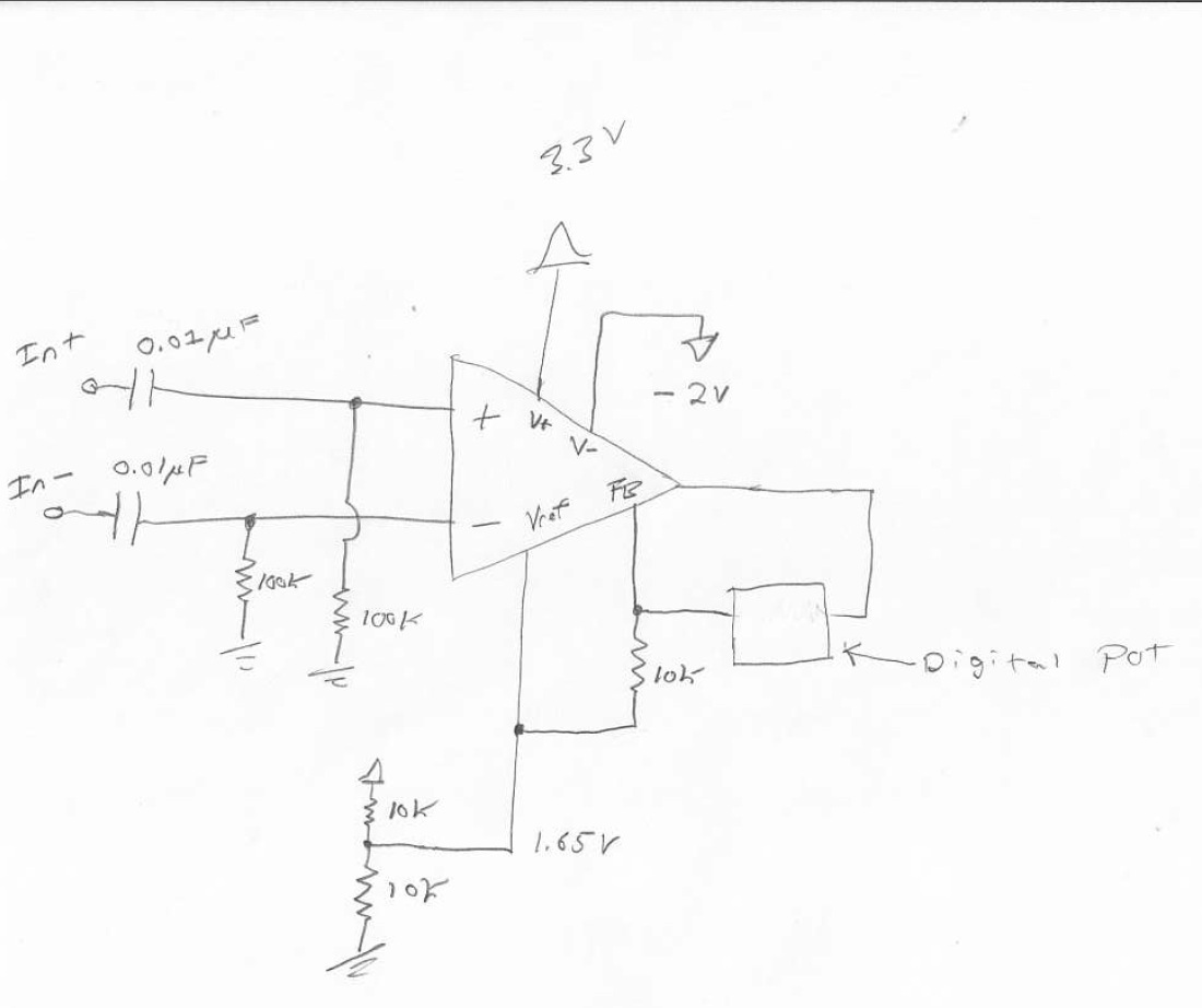
Here is a schematic of the functionality I'm looking for:

I need to receive an ac coupled signal from a differential sensor.  I then need to apply a gain of up to 10 to the signal.  I need the output to be at an offset of Vcc/2 (1.65V).  I'm looking for an output swing between 0v and my Vcc which is 3.3V.  I'm wondering if this part could accomplish something like this or if there is a better one in TI's portfolio.  My input bandwidth is only ~160Hz to 10kHz at a max gain of 10 so there won't be a lot of performance strain on the part.  The ac coupling allows me to eliminate the sensors input offset errors since only the ac content is really relevant.


Since the inputs to the amp will sit at 0V due to the AC coupling would I need V- to be negatively biased as shown above? 

Would I also be able to ground the inverting input and use the non-inverting for rough single ended functionality? 

Any direction/recommendations would be helpful.  Seems like a simple task, but so far this interface has been tricky. 

Does TI have any app notes regarding instrumentation amplifiers and their configurations?

  • Where in the INA826 data sheet can you find the maximum differential input voltage? Where can you find how close to the +/- power rails for this amp can the differential input voltage be. For example, the differential input on some chips all you to come within 1.2V or 1.5V of V+ and V-. I couldn't find this information.
  • Hello Robbie,

    Please refer to the following FAQ:

    e2e.ti.com/.../3373.understanding-instrumentation-amplifier-vcm-vs-vout-plots

    This link has a lot of excellent information about the linear operating region of instrumentation amplifiers. You will be particularly interested in the first 3 articles and the Vcm vs. Vout calculator tool.
  • Hello Peter,

    Thanks for the reply!  Almost, how do I figure out how wide/large of a differential input signal I can drive into the INA826?  I couldn't find this information in the data shee.

  • Those articles were helpful, but extremely brief.  If I use the INA826 and say I bias it with 3.3V and 0V with an offset of 3.3/2=1.65V and a gain of 1.  This is just an example.  Then I drive the inputs with two sine waves that are out of phase allowing me to have a "differential" signal.  180 degrees out of phase.  How do I figure out what magnitude (Vpp) those sine waves can go up to before the device stops operating correctly?  I know this depends on where your common mode voltage is because that determines your output swing, but in this case it is at 1/2 Vcc.  The data sheet for the 826 shows a similar scenario with 5V in figure 11.  In that figure, 2.5V (1/2 Vs for Vref) is within the square that says the output can operate pretty much from rail to rail (0V to 5V roughly). 

    I'm a little confused on how the differential signals (the actual input content of interest) correlates to all this.  If I satisfy the common mode requirements can I then drive sine waves (180 degrees out of phase) into the inputs that have rail to rail magnitudes therefore producing a full rail to rail output? 

    This may be a little hard to follow, but basically I'm ac coupling signals into the device so I can set the common mode voltage to be within the sweet spot of these plots, but how does this ac content (sine waves) I'm coupling in correlate to the reliable/proper operation of the device? 

    This is important because I'm having problems with an amplifier from another vendor that is expensive and isn't performing well.  I'm looking at replacing it with something TI offers and this amp would potentially be good. 

  • Hello Robbie,

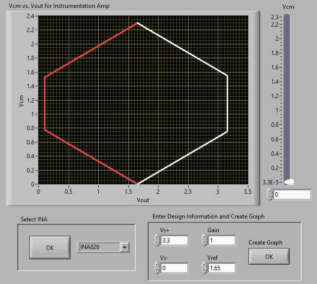
    The Vcm vs. Vout calculator tool (via the aforementioned FAQ) yields the following plot for the case you mention (single 3.3V supply, Vref=1.65, G=1V/V).

    As you noted, the output swing depends on the common-mode voltage. Since you're ac-coupling the input, single supply operation will not work because there is no linear output swing available at 0V common-mode.

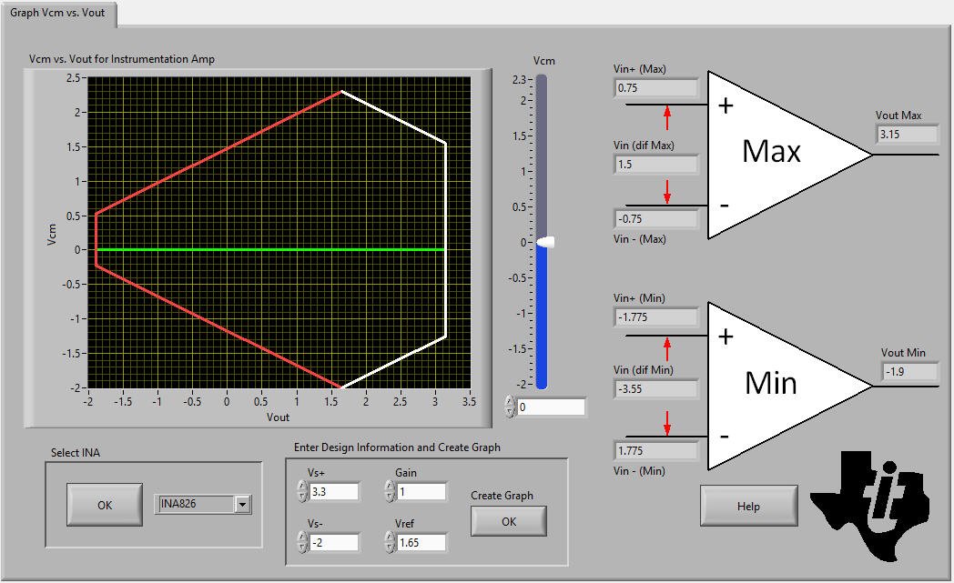
    If we return to your original circuit that has (V+)=3.3V, (V-)=-2V, Vref=1.65V, and G=1V/V the linear operating region now looks like this:

    You see that you now have a linear output swing from -1.9V<Vout<3.15V.

    Given the standard transfer function of an instrumentation amplifier:

    Vout=Vdiff*G+Vref

    We can re-arrange and solve for Vdiff:

    Vdiff=(Vout-Vref)/G

    I have supplied the Vout range and we know Vref and G. Therefore you should be able to determine the range of Vdiff, which is the difference between your two input sine waves.

    One final note...please understand that you should not drive Vref directly with a resistor divider. This is explained in section 8.3.7 the INA826 data sheet. Please use an op amp to buffer the voltage.

  • Hello Robbie,

    I forgot to mention that you may be interested in an alternate method for ac-coupling the inputs. This method preserves CMRR, which is typically degraded due to the mismatch between the input capacitors. Here is a link:

    http://www.ti.com/tool/TIPD191
  • Hey Pete,

    Thanks for a great write up!  I saw the amp requirement in the data sheet but totally forgot to draw it.  I think it needs a 5 ohm or less output impedance.  

    What if I biased the input pins at 1.2v?  So the vref is at vcc/2 and the inputs are DC biased at 1.2?  It looks like from that plot the sweet spot I want the common mode voltage in is 1.2v.  So if I bias both inputs then ac couple my input signals in would I have the best of both worlds?

    This would then mean my diff. Input voltage could be -1.65 to +1.65 in that example with a gain of 1?